Congratulations, team! We just won the contract to renovate those old warehouses on 99th Street into a new data center complex! When those buildings went up in the 1980s, they were the bee’s knees. All we’ll need to do is add some power, add some cooling, check out the sprinkler system, and Mega IT will be in business. No problem!
You, the fire sprinkler designer, wake up in a cold sweat knowing exactly what the problems are:
That vintage sprinkler system.
Pipe schedule design with small-diameter pipe.
No placards.
No design documentation.
Old backflow preventer — if it exists.
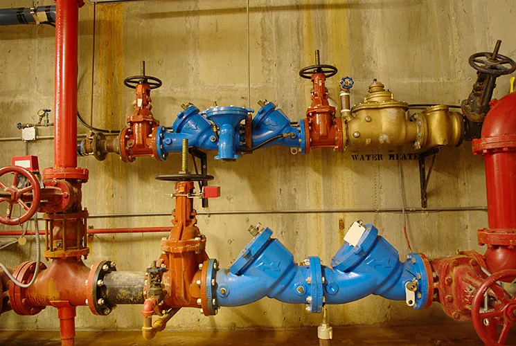
A riser crammed into a closet barely large enough for the equipment already there.
The water department will not allow a gleaming new data center to open unless the fire protection system protects the public water supply. That means adding a backflow preventer.

That also means more pressure loss.
And space.
Some existing systems were never hydraulically calculated. Some were designed around pipe schedules. Some have little or no remaining safety margin. Add a backflow preventer without understanding the available water supply, system demand and device pressure loss, and a system that once appeared adequate may fail to deliver.
Then there is the physical retrofit. Many older systems were packed into tight riser rooms that were never intended for backflow preventers. Backflow preventers require access to valves, test cocks and drains.
Fortunately, you are a problem solver, and this retrofit challenge has become easier to manage. Backflow preventer technology has improved. Many newer devices are smaller, lighter and less hydraulically punishing than older assemblies.
Let’s look at why backflow preventers are needed, why retrofitting them into older sprinkler systems can be challenging, and how today’s designers can reduce both the hydraulic and physical impacts.
Disgusting but effective against fire
Fire sprinkler systems present a unique challenge for water utilities. Inside sprinkler piping, water quality can be frankly disgusting. Corrosion products, scale, sediment and microbiological growth are common in stagnant systems. Some systems also contain antifreeze solutions or corrosion-inhibiting additives that utilities do not want entering the public water supply.
Under the wrong conditions, that scuzzy water can move the wrong way. A water main break, firefighting operation or period of heavy demand can reduce pressure in the public main. When that happens, water in a connected fire sprinkler system may reverse direction and flow back toward the public water supply.
Backflow preventers stop that from happening.
Water purveyors now commonly require approved backflow prevention assemblies on fire sprinkler services. However, much like the more than 40-year-old warehouse in our nightmare scenario, many older buildings predate those requirements. Some existing sprinkler systems have no backflow preventer; others rely on older single-check arrangements that no longer satisfy current regulations.
For decades, including into the 1980s, sprinkler systems were designed under very different assumptions than we use today. NFPA 13 published pipe schedules that prescribed pipe sizes based on hazard class and the number of sprinklers supplied, rather than requiring hydraulic calculations. Do you even remember NFPA 231C, the rack storage standard (RIP 1998)?
Those systems were not bad or wrong, just products of their time.
A system that has operated for 40 years may look dependable but nobody knows how much pressure is needed to operate. Designers must evaluate the system to confirm operating margin. The only way to find out is to verify the water supply, document the system and run the calculations.
The hydraulic penalty
Every backflow preventer takes pressure from the system. Designers can find that information in the manufacturer’s published flow curve data.
Properly sized fire protection backflow preventers often have relatively flat pressure loss characteristics across much of their flow range. That is good news. However, a system with 5 psi of safety margin cannot absorb a 9 psi device loss. The math has to work.
Pressure losses through early-generation and current backflow preventers are, surprisingly, not all that different. Here is a comparison of manufacturer-published reference materials for a commonly specified device: a 6-inch double-check assembly.
Vintage reference materials show pressure losses in the same general range as current devices in their intended flow range. Let’s review some examples.
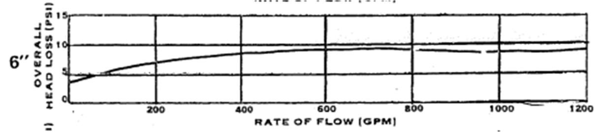
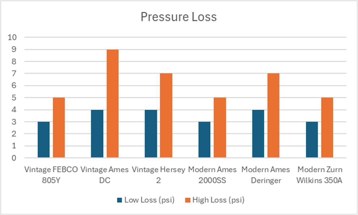
First, the venerable FEBCO 805Y used bolted-components in a spring-loaded Y-pattern check arrangement. The 805Y literature emphasized low head loss, ranging from 3 psi to 5 psi through its useful range, up to 1,000 gallons per minute (gpm).

Next, the Ames DC, manufactured until the mid-1980s, is an outlier. Pressure losses in this vintage unit were relatively higher than the competition, ranging from 4 psi to 9 psi across its useful range.
Finally, the Hersey Model 2, manufactured until the early 2000s, lands closer to the middle for pressure loss. Losses in this device ranged from 4 psi up to 7 psi in its useful range.
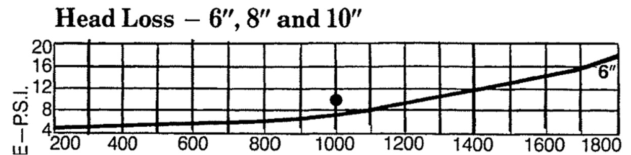
Looking at all three vintage devices, they create 3 psi to 9 psi pressure loss across the flow range, up to 1,000 gpm.
Next, let’s compare the published pressure loss curve in a few currently available models.
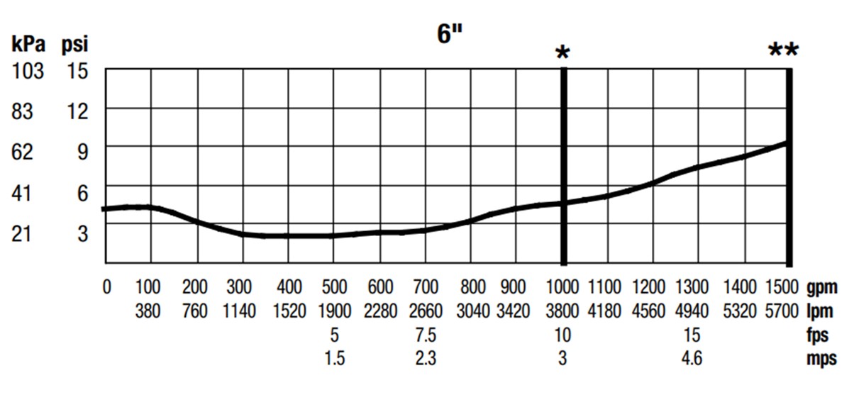
The Ames 2000SS Silver Bullet model has been on the market for over 30 years, and is still commonly specified and installed. The Ames 2000SS pressure loss curve shows why the pressure-loss story is not dramatic. The loss starts at 4 psi, similar to the vintage devices, then drops to less than 3 psi for a span of its flow range, before friction losses increase at the higher flow region up to 5 psi at 1,000 gpm.
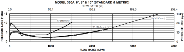
Zurn Wilkins 350A is another current model in the same neighborhood of pressure loss as the 2000SS. The published curve indicates a 3 psi to 5 psi loss across its operating range, up to 1,000 gpm.
Finally, the Ames Deringer 20, one of the newest models on the market, slots in with pressure loss ranging from 4 psi to 7 psi over its 1,000 gpm flow range.
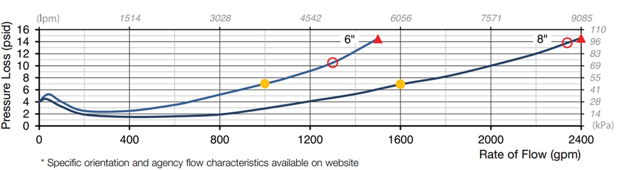
As shown in the graph, the pressure losses have not changed significantly over time. For the 6-inch devices reviewed here, the loss curves generally fall within a relatively narrow band, 4 psi to 7 psi, through the 1,000 gpm range. Some are better. Some are worse. None are magic.
So, if pressure loss is not the whole story, where did the big improvements happen?
Size. Weight. Access. Serviceability.
That is where the retrofit story gets interesting.
Size matters
If pressure loss has not changed dramatically, the physical package certainly has.
Backflow preventers live in riser rooms and closets, or in a corner of an old warehouse where someone already stuffed mechanical equipment, electrical panels, housekeeping pads and everything else that did not fit anywhere better.
Vintage assemblies could be enormous.
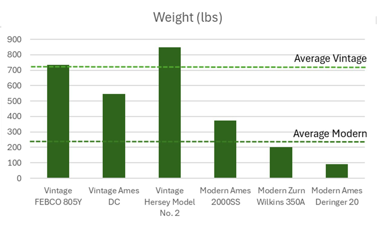
A 6-inch FEBCO 805Y measured nearly 60 inches long and weighed 735 pounds.
The Ames DC stretched to 66 inches and weighed “only” 547 pounds with valves.
The Hersey Model No. 2 measured 62 inches and could weigh 848 pounds with OS&Y valves.
These were not small accessories. They were heavy equipment.
Modern devices changed that conversation.
The 6-inch Ames 2000SS lists at just over 48 inches long and 375 pounds with OS&Y shutoff valves. Ames describes the 2000SS as having compact construction, short lay length and a lightweight stainless-steel body.
A Zurn Wilkins 350A is shorter still, with published dimensions around 47 inches and 362 pounds with OS&Y shutoff valves. Zurn describes the 350A as using a grooved, epoxy-coated ductile iron body and improved flow characteristics.
Ames Deringer 20 pushes the compact approach much further. The 6-inch grooved model is listed at only 29 inches long, and even I can lift it at only 90 pounds. Product literature emphasizes integral butterfly shutoff valves, short lay length and an all-stainless-steel body. Set it next to a vintage assembly and it barely looks like a backflow preventer.
That is the leap.
Not just a few pounds. Not just an inch or two.
Feet shorter. Hundreds of pounds lighter.
For a designer, these differences change the entire retrofit effort. Shorter assemblies fit where a vintage assembly cannot. A lighter assembly reduces the need for added support and rigging during installation. Integrated shutoff valves shrink the footprint to previously unheard-of dimensions.
Modern backflow preventers do not solve the retrofit problem, but they make it easier to solve.
In a cramped riser room, size matters.
Designing the retrofit
Similar to our example data center, backflow preventers can enter a project through a side door: A change of occupancy. A fire pump addition. An insurance requirement.
One change brings the existing sprinkler system into the light, and suddenly the system is in question:
Is the water supply still adequate?
Does the system still meet the hazard?
Does new equipment fit in the riser room?
That is the practical challenge in existing buildings. The backflow preventer doesn’t create the problem, but it may reveal the problem.
Fortunately, today’s designer has better tools.
Modern assemblies can reduce the physical burden. Current flow data can define the hydraulic impact. Updated calculations can show the remaining margin. However, the designer still has to connect those pieces.
The retrofit succeeds when the device fits the room, the pressure loss fits the calculation, and the finished system still protects the building.
Protect both systems
Backflow preventers do important work. They protect the public water supply from water that does not belong there. No one wants gross sprinkler water, filled with corrosion inhibitors, antifreeze or whatever else has been sitting in that pipe moving backward into the municipal system.
However, backflow preventers are not hydraulically free.
They take pressure. They take space. That does not make them the villain. It makes them part of the design.
A successful retrofit protects both systems: the public water supply and the fire sprinkler system. That requires current water supply information, a real survey of the existing system, manufacturer flow data and hydraulic calculations that include the device.
Modern backflow preventers give designers better tools than ever before. Shorter lay lengths. Lighter assemblies. Predictable pressure-loss data. Easier installations.
But the responsibility remains the same: the sprinkler system must work.
In many retrofit projects, the most significant hydraulic change is not the piping inside the building, it is the device added to protect the water supply feeding it.


