
You can enjoy the best comfort, the lowest energy costs and a competitive first cost. That may sound too good to be true, but with creative hydronic system design it is more than possible — and it has been demonstrated for more than 50 years with proven results.
Hydronic systems are the most comfortable and efficient for heating and cooling in the HVAC industry. They can be up to 40% more comfortable and 40% more efficient than air or refrigerant systems.
A case study of the Infosys Building in Hyderabad, India, and a Kentucky Call Center show similar savings: a 40% increase in energy efficiency and a 40% improvement in comfort with hydronic systems.
The Infosys Building hydronic system also achieved a reduction of 36% in electrical demand and impact on the electrical grid (https://bit.ly/4vHb6vD). Avoiding investments in traditional power generation and grid transmission expansions yields billions in cumulative infrastructure savings.
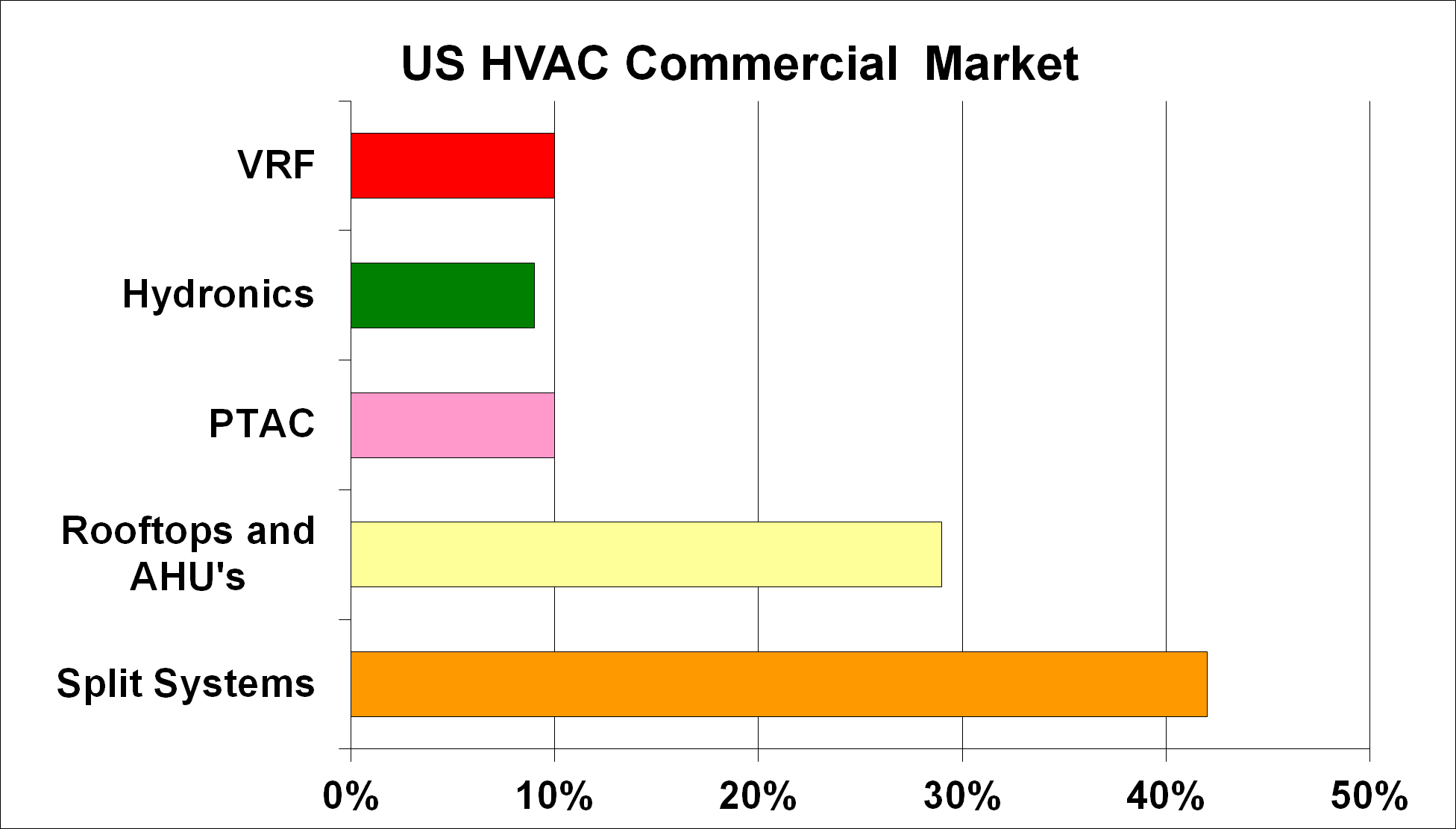
Again, hydronic systems are more comfortable and more efficient than air or refrigerant systems. Unfortunately, they have the lowest market share for HVAC systems because of first cost, estimated at less than 10% in the United States (see Figure 1). The challenge is to find a method to install a hydronic system that is competitive in first cost.
Obviously, if the amount of materials to install a hydronic system can be reduced, then the system’s cost will decrease.
To reduce ductwork, the industry offers ductless fan coils, and they can provide better comfort with individual zone controls for each unit.
The evolution of single-pipe hydronic systems
One of the first attempts to reduce materials and cost for piping was the single-pipe hydronic system, basically a primary-secondary piping system. It uses a single pipe for the primary circuit and two for the secondary circuit. Single-pipe circuits can eliminate up to 40% of piping in a hydronic system.
Bell & Gossett developed its Monoflo system in the 1940s and 1950s. It used Venturi tees in the primary pipe circuit to induce flow in the secondary piping circuit. It is a single-zone system in that flow in the primary system induces flow in all the secondary systems at the same time.
It gained popularity primarily as a residential hydronic heating system. There are thousands of Venturi tee heating systems installed throughout the United States. This author lived in a Monoflo-heated house that was extremely comfortable. Control valves can be added for individual zone control.
The evolution of single-pipe systems
Taco Comfort Solutions refined the single-pipe system by introducing the single-pipe LoadMatch system in the 1990s. The system uses maintenance-free wet-rotor circulators instead of less reliable control valves to regulate flow and temperature in the secondary circuits. The secondary circuit uses a Twin Tee for providing a hydraulically decoupled primary-to-secondary circuit fitting (see Figure 2).
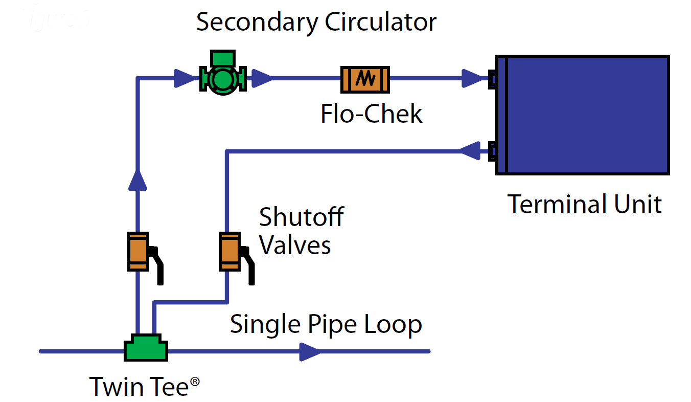
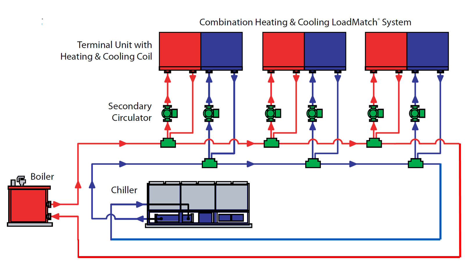
For commercial applications, simultaneous heating and cooling is provided by control of the wet rotor circulators for each heating or cooling coil in each terminal unit. No balance valves are required in the secondary circuits. The circulators are sized for the pressure drop of the secondary circuits. This is essentially a self-balancing system; balance valves don’t have to be tweaked to make occupants comfortable.
The system also requires substantially less pumping horsepower since there is no pressure drop for balancing or control valves.
This configuration reduces the number of HVAC pipe from four to two. The system can use any hydronic terminal unit, such as fan coils, air-handling units, chilled beams, radiant heating and cooling, etc.
International Environmental Corp. (IEC) also marketed its single-pipe SureFlow system, starting in the 1990s. The company combined its fan coil unit with a factory-mounted Taco wet-rotor circulator to provide a factory-packaged system.
Williams Comfort Products introduced its single-pipe ONDemand system starting in the 2000s. It also provided a factory-packaged system by combining its fan coil unit with a factory-mounted Taco wet-rotor circulator.
These systems have been operating since the 1990s, providing the best comfort available at competitive prices.
Taco, IEC and Williams teamed with HVAC Solution to create a software tool to produce a schematic piping diagram of the system: the Hydronic System Solution (HSS) software (see Figure 3). The tool also sizes, selects and schedules all the pipe and hydronic equipment. This significantly reduces the time needed to design and create bidding documents for the system.
Integrated piping: Making building systems do double duty
The second concept to reduce piping in a hydronic system is to use an integrated piping system (IPS). It uses another piping system in the building to do double duty for the HVAC piping system.
The first IPS was the American Air Filter Tri-Water system introduced in the 1970s. It used the fire protection piping to do double duty for a water-source heat pump. It is approved by NFPA 13, Standard for the Installation of Sprinkler Systems. Tri-water meant heating, cooling and fire protection in the same piping system. The system used the single-pipe fire protection main as the supply for the water-source heat pumps but required a second return line. This reduced the HVAC piping from two to one pipe, courtesy of the fire protection system.
Another approach to IPS was to use domestic water piping to do double duty for the HVAC piping. For buildings with larger domestic water loads, such as multifamily housing, hotels, motels, dormitories, etc., combining these two piping systems can yield substantial savings.
First Co. introduced its AquaTherm system in the 1970s. It used DHW to heat water for the fan coils. Cooling was provided by a split-system, direct-expansion cooling coil and air-cooled condenser. This reduced the total number of domestic water and HVAC pipes from six to four.
In the 1990s, Ultimate Comfort Systems used DHW for heating and fire protection piping for cooling to the fan coils. This reduced the number of domestic water and HVAC pipes from six to three.
Williams introduced domestic hot and cold water for HVAC piping in the 2000s for its IPS. This reduced the number of HVAC and domestic water piping from six to four.
Any IPS that uses domestic water piping must use NSF-approved components in the system, including the fan-coil piping, valves, circulators, etc.
Minimizing Legionella growth with IPS
Combining the two ideas of single pipe and integrated piping can further reduce the piping in an HVAC system.
Williams currently offers this combination as its IPS ONDemand system. Combining the single-pipe and IPS concept reduces the six-pipe system to just two pipes for both the HVAC and domestic water (see Figure 4).
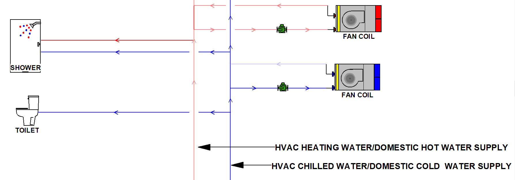
Using domestic water for HVAC needs also addresses the Legionella concern about DHW systems. ASHRAE Standard 188, Legionellosis: Risk Management for Building Water Systems, addresses these concerns. The biggest concern is the temperature of DHW distribution. Legionella thrives in water temperatures between approximately 75 F and 115 F. IPS uses water stored at 140 F.
Another major concern is stagnant water that allows the bacteria to grow. IPS continuously circulates water in the primary piping, avoiding possible stagnation that could occur in typical DHW mains.
Another point of possible stagnation could occur in the heating or cooling coils of the fan coil. Cycling the coil circulators once every 24 hours for up to five minutes, such as done in the ONDemand IPS, avoids water stagnation in the coils. This provides better protection from Legionella bacteria growth than a typical DHW system.
Design tools that simplify selection and documentation
Williams and Taco added the design of single pipe and IPS to the HSS software some time ago.
HVAC flow in gallons/minute (gpm) is calculated from the loads and the design delta T entered and selected by the designer. The domestic water flows are calculated from the Hunter Curve, converting fixture units to gpm. The software defaults the number of fixtures and fixture units from a wizard in the software, or the designer can choose the fixture counts. The flows are combined for each section of pipe and sized from conventional pipe sizing algorithms. The software completes all the calculations.
Using another wizard, the user can generate a flow diagram with all loads, flow, pipe sizes, equipment sizes and selections scheduled. This is possible by just answering a series of questions on the number and type of terminal units and the piping configuration.
Use of the HSS software significantly reduces the time to design and create bidding documents for the system.
Another software tool to compare first cost and operating costs is the Building Efficiency System Tool (BEST) developed by the RPA Hydronic Industry Alliance.
BEST won the Software Innovation Award at the 2025 AHR Exposition. A wizard allows the comparison of first, energy, maintenance and life cycle costs of HVAC systems.
Single pipe and IPS have been used in the industry for more than 50 years. Combining these proven systems yields significant benefits:
• Increased comfort using quiet variable-speed fans and lower airflow. Each zone is individually controlled with its own thermostat.
• Quiet operation by removing compressors from occupied spaces.
• Reduced first cost by significantly reducing the quantity of equipment, pipe, duct and time to install the system.
• Reduced startup and commissioning time from a self-balancing system.
• Ideal for retrofits, especially older buildings, because of less pipe, no ductwork and less conflict with other building components and existing structure.
• Increased energy savings from more efficient operating setpoints for heating and chilled water equipment. Lower pumping horsepower is due to lower pumping head, and lower fan horsepower is due to lower fan static pressure from ductless units.
• Increased value from better comfort and lower operating costs. This translates into higher operating income and higher resale value of the property.
• Creates the ideal building-side hydraulic interface to connect seamlessly into municipal-scale thermal trading loops or thermal energy networks (TENs).
Greg Cunniff, PE, is a systems engineer at Egg Geo. He has been in the HVAC and plumbing industry for over 50 years. He has worked and owned MEP consulting engineering, Manufacturer’s Representative, Controls and Building Management System contracting and Mechanical contracting firms. Greg can be reached at [email protected].