Have you ever walked onto a boiler job and been blown away by how great it looks? Have you looked long enough at a job to realize that despite how much pride was put into appearance, it wasn’t going to work well or at all? In most cases, it will still work well enough that no one will complain, but we can certainly do better than that!
One of the biggest concerns I see in boiler piping is in the application, or misapplication, of closely spaced tees. Closely spaced tees are a simple and effective way to incorporate hydraulic separation into your hydronic system. Hydraulic separation allows you to prevent circulator conflict, keep the boiler happy with its own dedicated circulator and maintain proper flow rates. This is all while dealing with flow imbalances when the system-side flow rates fluctuate in response to demands from various zones.
There are many ways to use closely spaced tees, and an equal number of ways to get it wrong. So, on top of making the job look great, let’s make it function as well! Here are a few things to consider when using them.
Sizing your tees and headers
Improper sizing can make your job go sideways real fast. We want to make sure that your tees and headers are not a restriction. A good rule is to size for velocities around 2 feet/second. Sizing your tees around higher velocities brings greater pressure drops and a higher likelihood of inducing flow from one side to the other.
This really defeats the purpose of hydraulic separation, no?
Undersized headers coupled with multiple circulators can also cause some grief. In some cases, and I’ve only seen one in person, one circulator can overpower an entire header, preventing flow to other zones even when their circulators are on! It was the most curious thing to see a circulator on with no flow to the corresponding zone until another circulator turned off.
Keep those tees close
Just as important as sizing is the placement of tees relative to one another and to nearby fittings. They don’t call them closely spaced tees for nothing! Most manuals recommend that tees be no more than four pipe diameters apart at the centers, up to 12 inches. I’ve seen many jobs where they’ve only noticed the part about 12 inches and installed them accordingly.
By keeping them close, your pressure drop between the tees will be low, providing the best-case scenario for hydraulic separation. The farther apart your tees are, the less the path of least resistance is known to the fluid in your pipe, and that fluid may decide to take a detour.
You also want to consider the proximity of fittings to your closely spaced tees. Due to space constraints, I see many installations where an elbow is placed directly adjacent to the runs of the tees. This can cause turbulence and possibly induce flow between the boiler and system loops, and vice versa. Typically, you’ll want eight pipe diameters upstream and four pipe diameters downstream of the tee runs.

Ensuring proper supply water temps
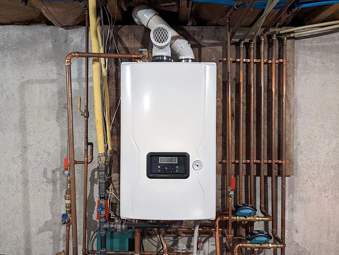
You may also see multiple sets of closely spaced tees in series. While this will still get you hydraulic separation between circuits, you may be in for a surprise. This is where you need to consider the difference between close tees in series versus parallel circuits.
When all circuits are on, closely spaced tees in series will have an interesting effect on the supply water temperatures to your heat emitters. As the flow from your heat source enters and exits the first set of tees, you won’t get the same supply water temperature at the second set. This can be advantageous if the supply water temperature requirements go down in subsequent sets of closely spaced tees, but this is rarely the case.
For the sake of conversation, let’s play it out. Maybe your first set of tees goes to a high-temp heat emitter, such as cast-iron radiators. The second set goes to panel rads, and the third set goes to in-floor heating. You can do the math to figure out the temperature drops from one set of tees to the next, and it may work out, but you’re counting on three different zones of heating to be on at the same time, all the time.
A more likely scenario is that the cast-iron rads will call for heat rather inconsistently, while the in-floor heat is always calling. This means you have a good chance of sending 180 F water to Mrs. Jones’ in-floor system and ruining her ultra-exotic floors from a country that I can’t even point to on a map.
Another possibility is that you have sets of closely spaced tees in series, serving zones that all require the same supply water temperature. Maybe it’s all fan coils or all in-floor heating. In either case, you will not be getting the same water temperature to all those heat emitters.
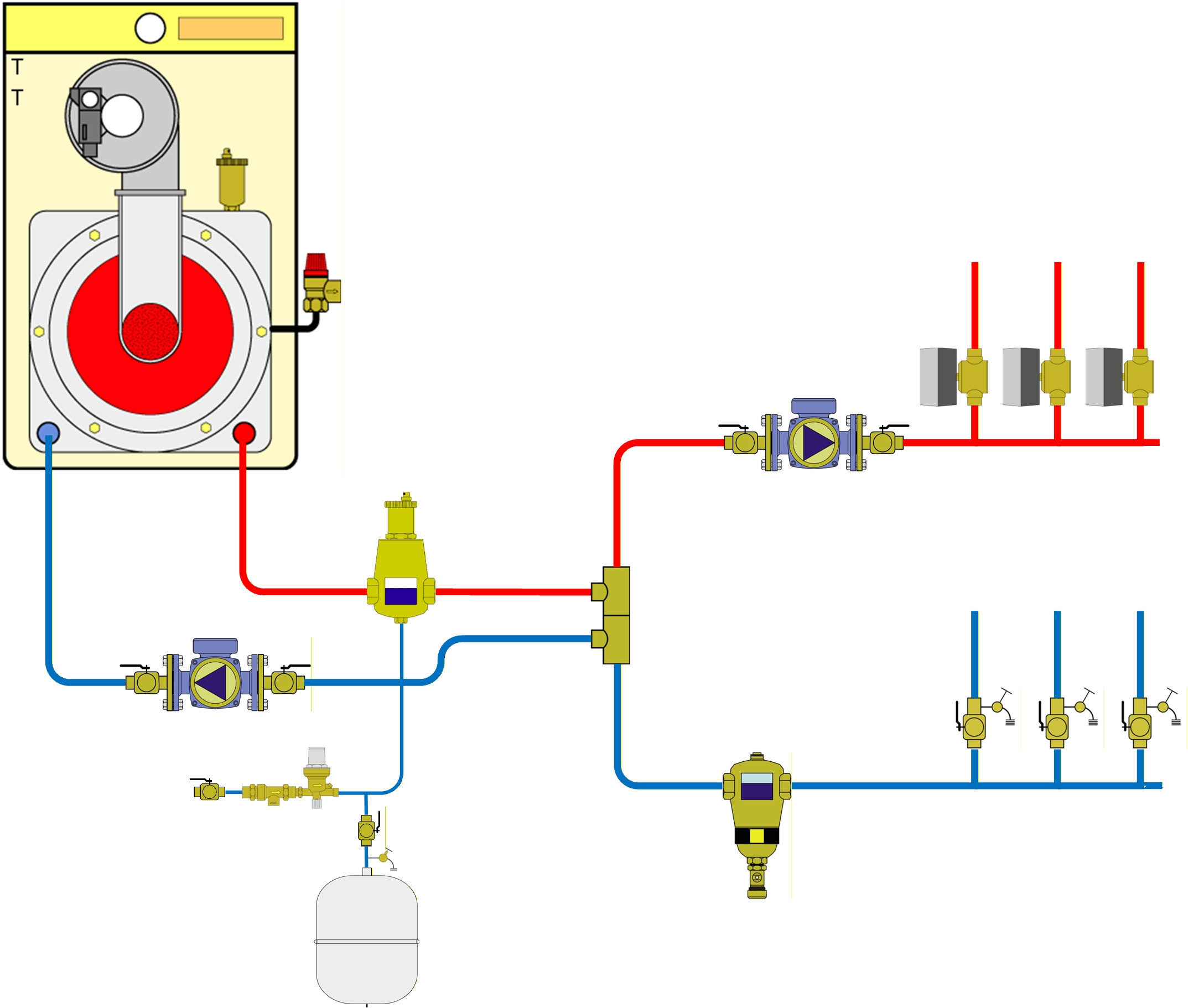
Instead, let’s start with a level playing field. Let’s make it simple and ensure the same water temperatures for each zone. Piping the zones in parallel on headers coming from a single set of closely spaced tees allows you to do this. You may still require different supply water temperatures for the various zones; however, you can deploy mixing valves to solve that problem.
Parallel loads and a single supply water temperature mean that the various zones can call for heat independently without affecting the others. This also allows for a simpler piping strategy that’s easy to understand and repeatable. Who doesn’t want that?
On your next design or installation, I would encourage you to get a second set of eyes on it. Question the things that you’ve known forever because that’s how the last guy did it. Be open to suggestions and remember that not all problems can be solved with the same solution.