In last month’s column, we covered a brief history of backflow prevention in the United States and how the plumbing industry responded over time, developing backflow devices and standards for adoption in plumbing codes. We also covered how the plumbing codes require specific backflow preventer types at various locations in the plumbing system, backflow prevention terminology and the five basic methods.
This month, we continue to cover the types of backflow prevention devices and the degree of backflow hazards they are designed to protect against. We also will discuss the product standards required by the plumbing codes, and provide examples of backflow incidents to show how backflow and back-siphonage can occur.
The degree of hazard is used in cross-connection programs to determine whether the substance is toxic, which is a health hazard, or nontoxic, which may be objectionable but is not a health hazard.
A toxic substance is any liquid, solid or gas that, when introduced into the water supply, creates or may create a danger to the health and well-being of the person using the water.
A nontoxic substance is any substance that, when introduced into the water supply, may create a non-health hazard, is a nuisance or is aesthetically objectionable. For example, food stuff, such as sugar, soda pop, etc.
Therefore, you must select the proper backflow device based on the type of connection and degree of hazard.
There are five basic backflow preventers (BFPs) or methods of backflow prevention that can be used to prevent backflow or back-siphonage:
- Air gap (method);
- Atmospheric vacuum breakers (including hose-type vacuum breakers) (device);
- Pressure vacuum breakers (device);
- Double check valve assembly (device);
- Reduced pressure zone assembly (device).
- The industry standards referenced in the plumbing codes and applied to most backflow prevention products are:
- ASSE (American Society of Sanitary Engineering)
- CSA (Canadian Standards Association)
- AWWA (American Water Works Association)
- IAPMO (International Association of Plumbing and Mechanical Officials)
- USC Foundation for Cross Connection Control
- FM (formerly, FM Global or Factory Mutual Insurance Co.)
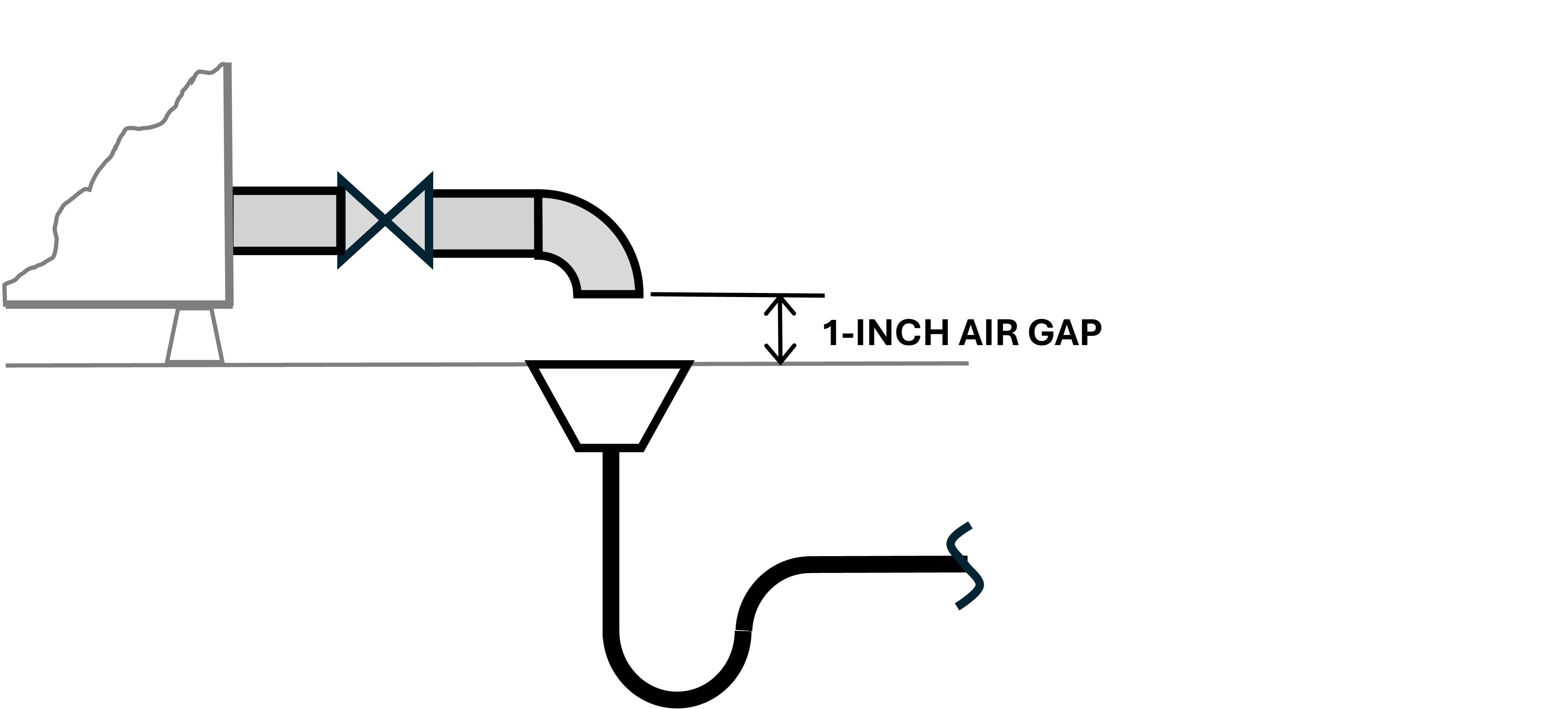
Air gap
An air gap is a method of protection of the water supply piping from back-siphonage or back-pressure in the downstream receptor. An air gap is not a device; it is a plumbing installation method. An air gap is the physical separation of the potable and nonpotable systems by an air space.
The vertical distance between the supply pipe and the flood level rim of the fixture or vessel should be two times the diameter of the supply pipe, but never less than 1 inch. The air gap can be used on a direct or inlet connection and for all toxic substances. An air gap is the best type of backflow prevention you can provide; however, in some cases, it may not be practical.
The industry standard for air gaps is from the American Society of Mechanical Engineers Standard ASME A112.1.2-2012 (R2022), Air Gaps in Plumbing Systems (for Plumbing Fixtures and Water-Connected Receptors).
Air break
An air break is a protection method for a food prep sink or open vessel from back pressure in a drain. It is not a device; it is a plumbing installation method. It is the physical separation of an open waste receptor or fixture that can drain into a floor sink, hub drain or floor drain as long as the point where it terminates is accessible for visible inspection and for cleaning.
With an air break, a vessel drained through an indirect waste can terminate with an air gap (physical vertical separation) or an air break inserted with the terminal end of the indirect drain below the flood rim of the waste receptor (floor sink, hub drain or floor drain). Open to the atmosphere and unable to siphon or experience negative pressure, the indirect drain from an open tank, fixture or vessel can drain to the potable and nonpotable systems through an air space or gap.
The industry standard for air breaks is ASME A112.1.2-2012. Air Gaps in Plumbing Systems (for Plumbing Fixtures and Water-Connected Receptors).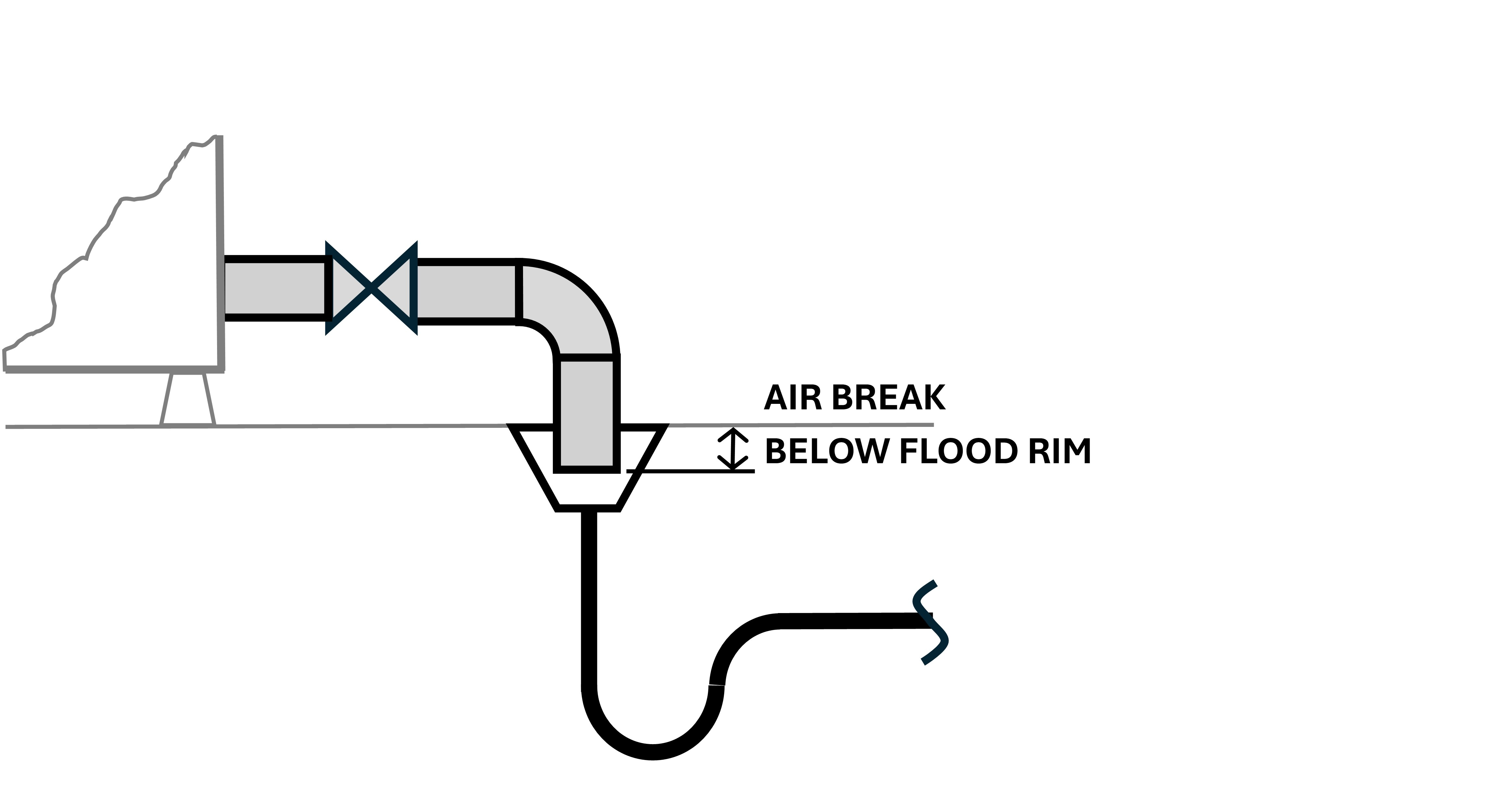
Hose valves with external hose thread vacuum breakers and nonfreeze wall hydrants
There are various types of hose valves: pipe-mounted, wall-mounted and frost-proof/nonfreeze.
All hose valves can be a source of cross-connection or backflow. Typically, a hose valve is supplied with 1/2-inch or 3/4-inch inlets, a 3/4-inch hose thread outlet and a valve to turn on, regulate or close off the water supply to a hose.
Hoses come with 3/4-inch hose threads. Hose valves, also known as hose bibbs, are basic, short valve-stemmed outdoor faucets. Some body styles offer an integral vacuum breaker for areas not subject to freezing. In areas where freezing is an issue, a nonfreeze or frost-free wall or yard hydrant can be used with a built-in vacuum breaker in the wall or yard hydrant.
The nonfreeze wall hydrants come with various shaft lengths to allow the valve seat to be shut off deep in the wall in a warm space when freezing is an issue. The standard for these devices is ASSE 1011-2004 Performance Requirements for Hose Connection Vacuum Breakers.
This standard applies only to those devices classified as “vacuum breakers, hose connection type,” which are designed to be installed on the discharge side of the hose bibb, hydrant or faucet that is fitted with hose threads. This device shall only be used on systems where the only source of low-head back pressure comes from an elevated hose equal to or less than 10 feet (3 meters) in height.
Hose valve/wall hydrant with integral vacuum breaker
Hose valves can come with an integral vacuum breaker or a hose-thread vacuum breaker installed on the hose threads. A hose-thread vacuum breaker should be installed on every hose valve to isolate garden-hose applications, thus protecting the potable water supply from contamination.
Garden hoses should not be left connected and pressurized with a trigger-operated hose valve or an on-off valve with a spray nozzle or chemical sprayer. Garden hoses should be disconnected after each use and when there is a potential for freezing weather.
If the device is of the nonremovable type, be sure it is equipped with a means to drain the line to prevent winter freezing, or simply remove the hose after each use.
Atmospheric vacuum breakers used with hose valves
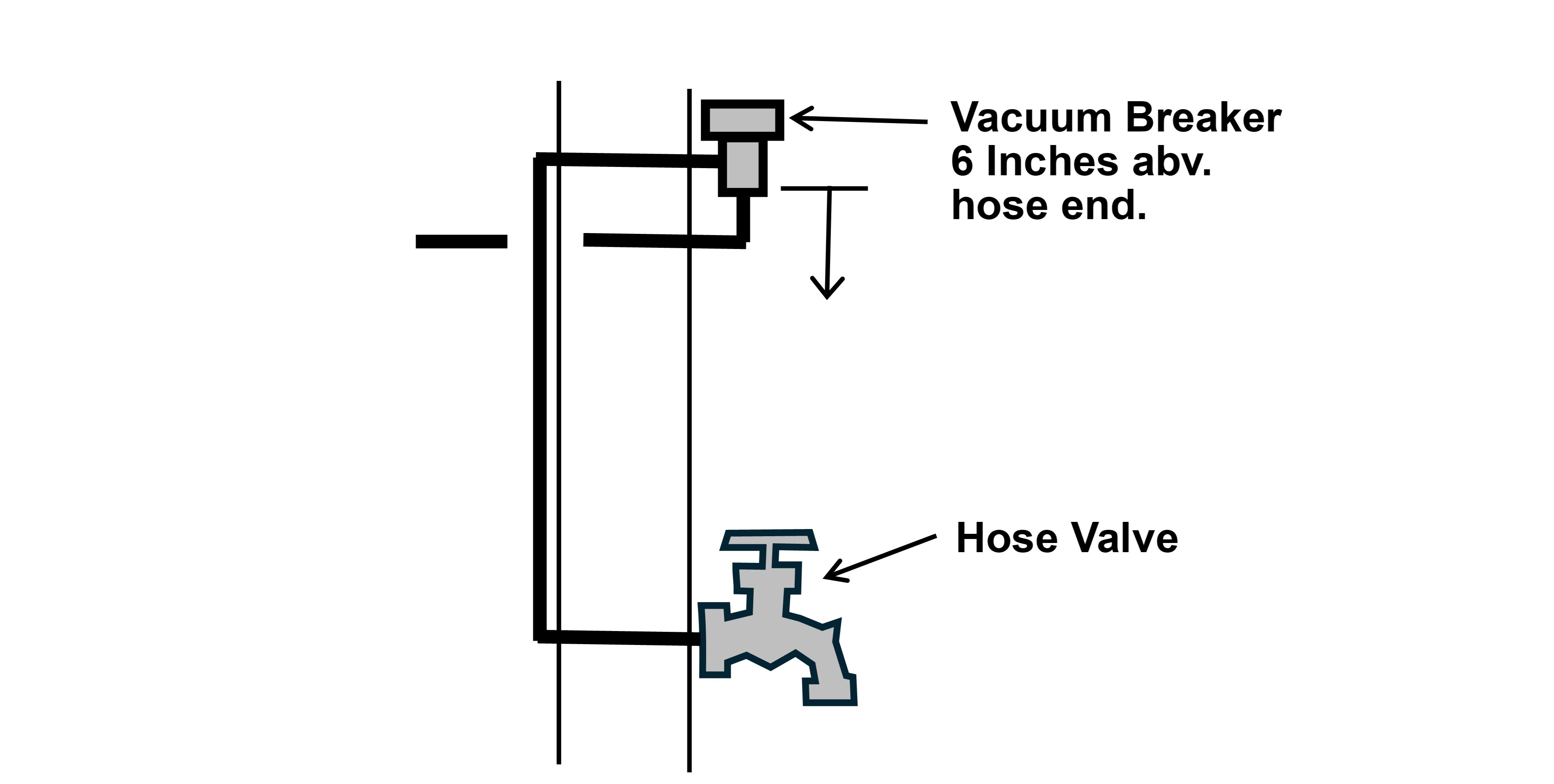
Technically, you can install an atmospheric vacuum breaker with a hose valve, but practically, the vacuum breaker must be located at least 6 inches above any location where the outlet end of the hose could be located in a pool, puddle, tank, etc., to allow the vacuum breaker to open up and introduce air when there is a negative pressure or a siphon condition present.
Installing a pipe-applied vacuum breaker at least 6 inches above the highest possible point where a hose could be would require raising the piping and the vacuum breaker to where it would come out of the wall, then connecting to a pipe-applied vacuum breaker, and finally back down to the hose valve. This piping arrangement is typically cost-prohibitive.
The more common option is to use a hose-thread vacuum breaker, which is a backflow preventer that screws directly onto outdoor faucets or a hose valve’s hose threads without major plumbing changes and at minimal cost.
Hose valve (hose bibb) vacuum breaker, maintenance
The purpose of a hose valve is to permit easy attachment of a hose for outside lawn watering, or pavement or building exterior cleaning purposes. However, a garden hose can be extremely hazardous when it is left submerged in swimming pools and chemical tanks, in elevated locations (above the hose valve), left running while watering shrubs or when lawn chemical sprayers are attached to hoses for fertilizing and weed chemicals (biocides).
When a hose is left lying on the ground in puddles with contaminants such as animal waste, fertilizer, insecticides, biocides or other garden chemicals, a water main break or a large fire can cause the water pressure in the water main to drop below the pressure at the home and siphon the contaminants back into the piping system.
Under certain piping conditions, a Venturi or siphon can develop at a hole, opening or tee in a pipe, where flow past the opening or branch can cause negative pressure due to the Venturi effect. The Venturi effect can siphon contaminants from the branch into the drinking water supply pipe.
This is why a vacuum breaker should be used on hose valves. Before freezing weather, remove the hose and allow the valve to drain to prevent freezing and cracking of the valve body. If the device is equipped with a means to permit the line to drain after the hose valve is shut off, a removable-type hose valve vacuum breaker could allow the part of the hydrant downstream of the shut-off valve to be drained, but the user must remove the hose to allow for draining the hydrant body.
If the hose is not removed, it defeats the purpose of the nonfreeze hydrant feature. All water management and preventative maintenance plans should call for the removal of all outside hoses before freezing weather. If the vacuum breaker is of the nonremovable type, be sure it is equipped with a means to drain the line to prevent freezing in winter.
For belowground piping, add service valves and tees in locations to allow the use of low-pressure air about 5 psi per floor level for buildings (a maximum of 10 psi to prevent water hammer damage to piping, equipment and valves) and up to two basement levels to blow out the underground and trapped water and winterize the piping exposed to freezing.
For aboveground piping, add drain valves at low points to allow gravity draining of all trapped pipes subject to freezing or add valves and tees to allow low-pressure air to blow out the water and winterize the piping exposed to freezing.
Atmospheric vacuum breaker
The most used type of backflow preventer is the atmospheric vacuum breaker (AVB). It incorporates an atmospheric vent, a floating valve seat and a sealing gasket that functions like a lift check valve. The AVB depends on a supply of potable water pressure to force the floating lift check valve up, sealing off the atmospheric vent inlet. The water then passes through an outlet in the side of the AVB body and flows to downstream equipment.
When a negative pressure develops in the supply line, the loss of pressure permits the lift check valve to drop, opening the vent inlet and admitting air to the system to break the siphon or vacuum. The industry standard for AVBs is from the American Society of Sanitary Engineering, Standard ASSE 1001-2021 — Atmospheric Type Vacuum Breakers.
ASSE 1001-2021 applies to atmospheric-type vacuum breakers (herein referred to as the “device”) that are single pipe-applied, flushometer-applied or integrally-applied (does not apply to water closet tank fill valves, tank or basin fill valves or similar devices that depend on float-operated valves to control flow).
Float-operated valves are downstream valves that can allow continuous backpressure on the device. The purpose of these devices is to protect the potable water supply from pollutants or contaminants that enter the system due to back-siphonage through the outlet.
Under back-siphonage conditions, air enters the piping system when negative pressure is present. A small amount of water is permitted to exit through the air openings (ports) when they activate, so they should be located where the water will not cause damage.
AVB limitations
AVBs work with intermittent pressure when an upstream valve shuts off. If negative pressure in the water main (from a fire or water main break) causes a siphon, the device opens to let air into the pipe, interrupting or stopping the siphon.
These vacuum breakers must not be used where there is a potential for higher downstream pressure or an increase in downstream pressure. This is because the pressure will be continuous and will hold the lift check valve up in the closed position, and the valve will allow the downstream pressure to flow back through the valve, permitting the back-pressure backflow of contaminants to pass through the vacuum breaker into the potable water supply line.
AVBs are not suitable when there is a downstream valve or continuous pressure application because long-term pressure on the gasket can cause it to stick against the seat. The AVB may not open when a negative pressure/siphon occurs in a critical backflow situation.
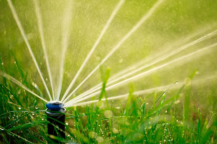
Lawn sprinkler systems
AVBs can be used on lawn sprinkler systems if they are installed downstream of the zone valves and not subject to continuous pressure. They must also be installed at least 6 inches above the highest sprinkler head in the system and must have no control valves located downstream of the device to protect the potable water supply.
Pressure vacuum breakers (PVBs) can be used on zone valves for lawn sprinkler systems under continuous pressure. When PVBs are installed on the zone valve for an irrigation system, they must be installed 12 inches above the highest sprinkler head. Many installations fail because the valves are installed 12 inches above the ground rather than 12 inches above the highest sprinkler head.
Single check valves
Most jurisdictions require backflow protection on all boiler feed lines for many reasons because boilers produce high-temperature boiler water and often have corrosion inhibitors or other toxic chemicals added. They can all pose a hazard in a backflow incident.
Some jurisdictions will allow a dual-check backflow preventer with intermediate atmospheric vent as minimum protection for residential boilers. A reduced-pressure backflow preventer is generally required on the make-up water connection to commercial and combination heating hot water and domestic hot water boilers. However, low-cost, continuous-pressure dual-check backflow preventers are now available.
Next month, we will continue with Part 3 and cover double-check valve assemblies, reduced-pressure zone assemblies and examples of cross-connections.
Reminder: The code changes for the 2030 codes are due the first week in January 2027; that’s only a few months from now. So, get those code change mark-ups ready. The online code change process for both model codes should be available in the fall 2026.