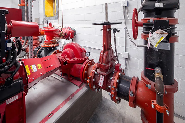
If you’ve spent any time around fire pump submittals or fire pump rooms, chances are you’ve probably run into this scenario. You are staring at a hydraulic calculation showing that the system working pressure exceeds 175 psi. The easiest fix on paper is to install a pressure-reducing valve somewhere on the pump’s discharge side. Problem solved, right?
Not quite. NFPA 20, the Standard for the Installation of Stationary Pumps for Fire Protection, has been pretty clear on this for a while, and the 2025 edition leaves no room for interpretation. You can’t use a pressure-regulating device in the fire pump installation to satisfy the standard’s maximum pressure requirements.
This sentence trips people up constantly, partly because pressure-regulating devices are perfectly acceptable in plenty of other places within a fire protection system. The trick is knowing where the line is drawn and why it’s drawn there.
This column walks through that distinction. We’ll start with terminology because the words matter more than people realize. Then we’ll look at what NFPA 20 actually requires, where pressure-regulating devices are allowed (and sometimes required) under NFPA 13, Standard for the Installation of Sprinkler Systems and NFPA 14, Standard for the Installation of Standpipe and Hose Systems, and what all this means for inspection and testing down the road.
The words matter more than you think
Four main terms come up in any conversation about pressure management, and they are used interchangeably far more often than they should be. Each one means something specific in the standards, and the differences have real consequences.
A pressure regulating device is the broad parent category. NFPA defines it as a device designed to reduce, regulate, control or restrict water pressure. It’s deliberately broad. When NFPA 20 prohibits pressure-regulating devices in the fire pump installation, the umbrella term is encompassing.
A pressure reducing valve, or PRV, is the most familiar member of the family. It’s defined as a valve that reduces downstream pressure under both flowing and nonflowing conditions. The “and” part is the key. A PRV limits both the downstream static and residual pressure in the system.
A pressure control valve is a pilot-operated PRV. It is defined as a pilot-operated valve that reduces downstream pressure to a specific value under both flowing and nonflowing conditions. These types of valves are normally better for pressure regulation.
A relief valve works differently than a PRV. It is defined as a device that diverts liquid to limit excess pressure in a system. A relief valve does not restrict, regulate or control flow to reduce pressure in a system. Instead, it releases liquid (water) from the system to reduce its pressure.
NFPA 20 defines two distinct types of relief valve, and the distinction matters. A circulation relief valve is a small valve, separate from and independent of the main relief valve, used to cool a pump by discharging a small quantity of water. It has nothing to do with overpressure protection.
The main relief valve is the one most practitioners mean when they talk about relief valves on fire pumps: a device designed to automatically relieve excessive pressure caused by an overspeed condition in the driver or engine. It remains closed during normal operation and opens only when pressure exceeds its set point, discharging water to the environment or back to suction until conditions settle.
While all these devices reduce system pressure, they do so in different ways and are used in different applications. Words matter, and the wrong words here will lead to the wrong result in the system.
What NFPA 20 actually requires
Fire pumps exist to make up the difference between what the water supply provides and what the system needs. To do so, they need sufficient pressure to overcome elevation and friction losses and to provide the residual pressure required at the most remote point of the system, such as a sprinkler, nozzle or hose valve. Pumps are sized accordingly, and their performance follows a characteristic curve.
NFPA 20 requires a pump to produce at least 65% of rated pressure at 150% of rated flow, with shutoff (churn) pressure not exceeding 140% of rated pressure.
This churn pressure is where overpressure problems usually start. Section 4.7.7.1 states that the net pump shutoff pressure plus the maximum static suction pressure, adjusted for elevation, can’t exceed the rating of any system component on the discharge side. In other words, the worst-case pressure the pump can produce, combined with the highest pressure the suction side could be contributing, has to stay within what every fitting, valve, sprinkler and length of pipe downstream is rated for.
NFPA 20 also requires a main relief valve in specific situations, particularly on diesel-driven pumps, where there’s the possibility that the engine can run at up to 10% above rated speed. Because centrifugal pump pressure scales with the square of shaft speed, a 10% speed increase produces a 21% pressure increase (1.1² = 1.21).
Section 4.20.1.2, therefore, requires a main relief valve when 121% of the net rated shutoff (churn) pressure, combined with the maximum static suction pressure adjusted for elevation, exceeds the pressure rating of the system components.
Most sprinklers are rated for 175 psi. They are often your “weakest link,” as many types of sprinklers are not available with higher-pressure listings or are limited by NFPA 13. You can specify components rated at 300 psi, and in high-rise work or in jurisdictions with strong municipal water supplies, you often have to. This is why a water supply analysis by the engineer of record is critical early on in the construction phase.
Why you can’t add a PRV after the pump
So, back to our original scenario. The numbers don’t work, the pressure is too high and a PRV would solve it. Why doesn’t the standard let you do that?
Section 4.7.7.2 spells out the prohibition: “Pressure relief valves and pressure-regulating devices in the fire pump installation shall not be used as a means to meet the requirements of 4.7.7.1.”
On the suction side, the boundary is defined by Section 4.16.1.1: the suction components consist of all pipe, valves and fittings from the pump suction flange back to the connection to the public or private water service main, storage tank, reservoir or other water source feeding the pump.
Where pumps are installed in series, Section 4.16.1.2 clarifies that the suction pipe for each subsequent pump begins at the system side of the discharge valve of the previous pump, meaning the discharge assembly of the upstream pump is its own installation, and the downstream pump’s suction components start where that assembly ends.
On the discharge side, the fire pump installation extends from the pump discharge flange to and including the discharge isolation valve (also referred to as the discharge control valve). Everything between the pump discharge flange and that valve is inside the prohibition. Once you’re downstream of the discharge isolation valve, you’re outside the fire pump installation, and the restriction no longer applies.
NFPA 20 makes this explicit in the Annex A note to 4.7.7.2: “It is not the intent of this subsection to restrict the use of pressure-reducing valves downstream of the discharge isolation valve for the purpose of meeting the requirements of 4.7.7.” This is not a loophole; it is the intended scope of the prohibition. PRVs installed downstream of the discharge isolation valve in the fire protection system are permitted, but usually not recommended.
The reasoning behind the prohibition itself comes down to two things, reliability and verifiability.
Pressure-regulating devices are mechanical. They have moving parts, ones that can foul, stick or fail in a partially closed position, which is the worst-case failure mode because it restricts flow during the one event the system was built for.
A pressure-regulating device installed downstream of the fire pump discharge control valve adds friction that must be accounted for in the hydraulic calculations. The added friction loss can drive increases in pipe sizing or eat into the pressure safety margin in the calculations.
Beyond the hydraulic penalty, a regulating device sitting between the pump and the test header obscures what the pump itself is actually doing. The acceptance test under NFPA 20 and the annual flow test under NFPA 25 both depend on observing the pump perform, directly reading pressure and flow at the pump, not downstream of a device reshaping the curve. A regulating device in that location complicates the test and makes diagnosis harder when a fire pump doesn’t perform as required.
It is also worth knowing how long this prohibition has been enforced. Annex note A.4.7.7 explains: the prohibition was codified in the 2003 edition of NFPA 20. Before that, the 1999 edition recognized the use of pressure relief valves for pressure management at churn or low flow as a poor design practice; however, it did not strictly prohibit it. Installations designed under those earlier editions and containing pressure relief valves for that purpose are still in service today.
Section 4.17 covers discharge pipe and fittings in detail, including the pipe, valves, fittings and testing. Section 4.17.11 makes the prohibition explicit at the component level: “No pressure-regulating devices shall be installed in the discharge pipe except as permitted in this standard.” This is a direct prohibition, not an oversight into how the section is organized.
When the pressure analysis indicates a problem, the fix must come from somewhere other than a regulating device on the discharge side. The usual options are:
• Increase component ratings. Specify sufficient psi piping, fittings and valves based on the maximum system working pressure.
• Pick a different pump. A pump with a flatter curve, or one whose churn pressure is closer to its rated pressure.
• Zone the system. This is the standard answer for high-rise work. Express risers, zoned systems and intermediate pumps or break tanks can help to keep any single zone within its component ratings.
• Look at the suction side. A break tank can eliminate municipal static pressure’s contribution to the discharge total in some cases.
Where pressure-regulating devices are still welcome
The prohibition in NFPA 20 is narrow; it applies to the fire pump installation. Once you’re downstream of that boundary, NFPA 14 and NFPA 13 provide the requirements for the use of pressure-regulating devices in their respective applications.
The 2024 edition of NFPA 14 sets the thresholds for standpipe hose connections. A pressure-regulating device is required at a 1 1/2-inch hose connection when residual pressure would exceed 100 psi, and at a 2 1/2-inch hose connection when static pressure would exceed 175 psi. Those numbers stem from inherent safety issues firefighters could encounter at higher pressures.
Anyone who has tried to manage a 2 1/2-inch line at high pressure understands why this requirement exists. These requirements often need to be applied to applications such as mid-rise and high-rise hotels, hospitals, parking structures and other buildings where the working pressure limitations are exceeded.
NFPA 13 handles the sprinkler side. When pressures at sprinklers or other components exceed their working pressure rating (again, typically 175 psi for most sprinklers and some piping), the design either steps up to higher-rated components or limits downstream pressure with a regulating device. This is typical of systems in high rises. On the lower floors of a tall building, pump pressure plus elevation head can easily push you past standard ratings, and a PRV at the floor control assembly is often the easiest answer.
What this means for inspection and testing
Pressure-regulating devices that are properly installed don’t get to sit and be forgotten, although I am sure we have all seen some that have. NFPA 25 requires periodic inspection, testing and maintenance (ITM), and the requirements are more involved than people sometimes assume.
Under NFPA 25, full-flow testing of PRVs is required every five years; however, master pressure-reducing devices shall be flow-tested annually. The applicable testing interval and method depends on the valve type and on the edition of NFPA 25 adopted by your authority having jurisdiction. Always verify the local adoption before setting up an ITM schedule.
The point of all this testing is to confirm that the device is still doing what it was designed to do, that internal components haven’t deteriorated and that nothing has fouled or seized in a way that would matter during an actual fire.
Performance, not failure
If you take three things away from this, take these.
• As I was lucky to learn early in my career, words matter and definitions have meaning. Pressure-regulating device, pressure reducing valve, pressure control valve, circulation relief valve and main relief valve each have specific meanings under the 2025 edition of NFPA 20.
• The prohibition on using relief valves or pressure-regulating devices to meet maximum pressure requirements at the pump is mandatory, as stated in the 2025 edition. When the numbers come out too high, the answer is in pump selection, component ratings or system zoning. It’s not in adding a PRV to the discharge piping.
• Pressure-regulating devices belong at the point of use — standpipe hose connections, sprinkler system zones or anywhere the components or the firefighters using them need pressure held within a specific range. The standards permit them and, in many cases, require them in those locations.
Fire protection systems get judged on how they perform during a fire, not on how they look on a routine Tuesday afternoon. The requirements in NFPA 20 exist because somewhere along the way, someone watched a system fail and figured out why. Following them isn’t bureaucratic compliance. It’s what makes the system work when it must.
Michael Newell is the owner of Belvedere LLC, a fire and life safety consulting firm in Houston. He holds NICET Level IV certification in Water-Based Systems Layout and serves on several NFPA technical committees, covering NFPA 13, 13R, 13D, 24, 291 and 1142. He also serves on the NFSA Training and Education, Future Leadership, and Engineering & Standards Committees, as well as the AFSA Technical Advisory Council.