Domestic hot water recirculation (DHWR) systems are designed to conveniently provide a hot water supply at every fixture in all units of a building. The purpose of these systems is not only to allow for instant hot water at the turn of a tap but also to conserve the amount of water wasted while waiting for a shower, bath, sink or any other water faucet to heat up.
Considered one of the best practices in commercial, residential and institutional buildings, DHWR systems guarantee occupant comfort, health care, safety and code compliance, as well as water and energy conservation.
A properly designed DHWR system should:
• Provide adequate amounts of water at the prescribed temperature to all fixtures and equipment during all times of use;
• Use an economical hot water source;
• Adapt to changing conditions;
• Provide a cost-effective, efficient and lasting installation;
• Provide an economical operating system with reasonable maintenance;
• Minimize risk to those using the fixtures it serves.
An efficient DHWS design typically includes a hot water source such as an automatic storage water heater, booster heater, boilers, etc., supply piping, thermostatic mixing valves, recirculating pumps, return piping and balancing valves to regulate flow in each branch to offset heat loss.
The Need for Balancing
Domestic hot water systems need to be properly balanced to ensure hot water is readily available on demand on every floor in a building. Typically relying on multiple branches off the hot water supply line, these systems need a device that can respond dynamically to changing conditions.
Since water flows in the path of least resistance, traditional fixed balancing valves struggle to keep up in these open systems, requiring them to be manually balanced and rebalanced repeatedly. This often leads to pricey labor costs and frequent callbacks as the dynamics of system usage render the initial balancing inadequate.
Today, thermostatic balancing is the preferred method as it requires a single valve to automatically balance a DHWS. It adjusts system flow to maintain a set temperature at the end of each supply branch. Thermostatic balancing valves eliminate the need for manual balancing costs while ensuring a properly self-balanced system for buildings.
These devices account for heat loss in transit to fixtures, as well as paths of least resistance. As recirculating systems have become critical to building design, it is important to understand the requirements and constraints.
DHWR Design Considerations
When designing a recirculation system, you should consider the many factors related to flow calculation, pressure loss and recirculation pump sizing. It is typically recommended to use traditional pipe sizing and head loss practices to determine pressure loss in the recirculation system. The American Society of Plumbing Engineers and the American Society of Heating, Refrigerating and Air Conditioning Engineers also provide design guides widely accepted and recommended in DHWR system design.
1. Calculating pressure loss across the valve. It is important to calculate the flow required to offset heat loss at the end of each branch. Appropriately balancing flow will ensure no short-circuiting of hot water through the path of least resistance. Minimizing flow velocity should also be considered to prevent any erosion in copper piping. Erosion can occur when high water velocities and hot water mix in the copper piping.
2. Recirculation pump sizing. Hot water recirculation pumps allow an immediate supply of hot water to all fixtures by pumping hot water through the hot water piping system and back to the heater. Appropriately sizing the pump in a DHWR system can save a lot of time and money in the long run.
To ensure a well-designed recirculation system, the pump must be properly sized to provide sufficient flow to compensate for the total heat loss in all the supply branches to the furthest fixture in each circuit. An undersized pump can result in recirculated water not staying warm enough, while oversized pumps are unnecessarily expensive because they typically need to be constructed with specific nonferrous materials.
The required flow rate formula is gallons/minute (gpm) = BTU/hr./(∆T x 500).
A common design practice for domestic hot water recirculation systems is to use ∆T = 5 F. This is the temperature difference of the recirculating water between the heat source and the furthest fixture in each circuit.
Assuming this common value of a ∆T = 5F, the above equation simplifies to gpm = BTU/hr./2500. If the designer prefers a ∆T = 10 F, the above equation simplifies to gpm = BTU/hr./5000.
Note that if a lower temperature drop is specified, this requires a higher flow rate. The BTU/hr. heat loss will vary based on pipe type, size, length and insulation. The heat loss table below is used only to demonstrate example calculations and should not be referenced for real-world BTU/hr. heat loss.
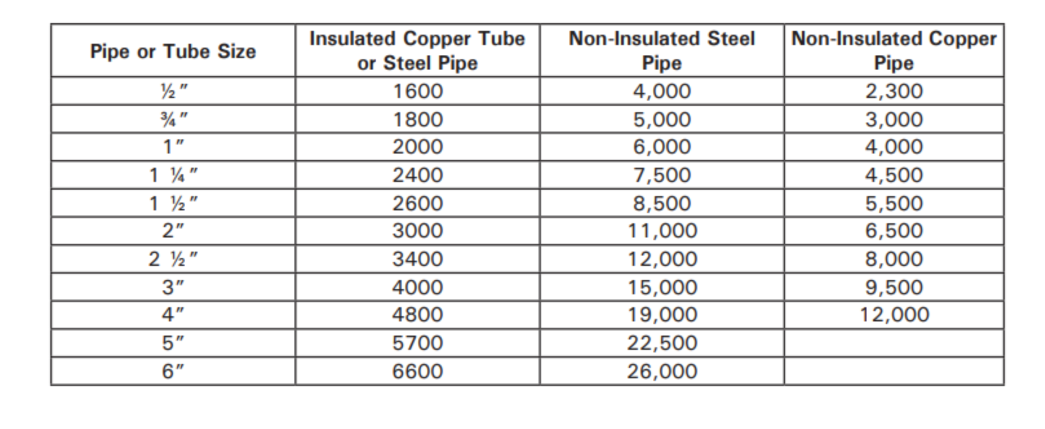
For example: Calculate the recirculation flow rate required for ∆T = 10 F for 200 feet of 1/2-inch, noninsulated copper pipe. Determine the pressure drop across a 1/2-inch thermostatic balancing valve at that flow rate. Use the chart for heat loss of 2,300 BTU/hr. per 100 feet (x2 for 200 feet) and the flow rate equation for temperature drop of ∆T = 10 F. Flow rate = 4600 5000 = 0.92 gpm flow required in that circuit.
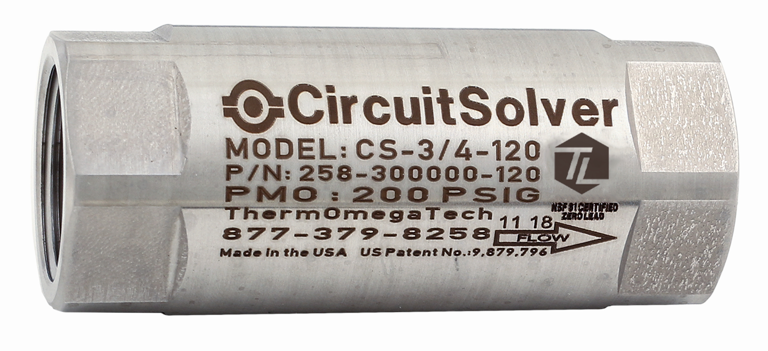
For this example, we will use a 1/2-inch CircuitSolver balancing valve which has a design Cv = 0.6; pressure drop = (0.92/0.6)2 = 2.3 pounds/square inch (psi).
Conclusion: Pressure drop across a 1/2-inch CircuitSolver with design Cv = 0.6 and branch flow of 0.92 gpm is 2.3 psi.
Following the recommended design guidelines to appropriately size circulator pumps will ensure an efficient and economical thermostatically balanced DHWS system for commercial, residential and institutional buildings while guaranteeing immediate hot water on every floor at every fixture.
Aaron Markward joined the ThermOmegaTech team in 2018 after graduating from Temple University's Fox School of Business. Markward is now the national sales manager for the commercial plumbing division. He supports 27 manufacturers’ representative agencies across the United States and Canada to help advance the plumbing industry to the most efficient solutions for plumbing designs. For more information, email ThermOmegaTech at [email protected].


