Before we get into fire pump sizing, let’s delve into the purpose of a fire pump. A fire pump is specialized equipment used to boost the water pressure in fire protection systems so that fire sprinklers, hoses and other equipment receive adequate water flow during emergencies. This is crucial in tall buildings or large facilities where the municipal water supply or storage tanks may not naturally provide the required pressure for effective fire suppression.
The main functions are:
• To increase water pressure and flow to ensure firefighting systems work efficiently, especially in high-rise structures or areas with insufficient water supply;
• To automatically activate when system pressure drops as fire protection equipment (such as sprinklers or hoses) is engaged;
• To ensure that water reaches all necessary parts of a building or facility for effective fire control.
Fire pumps are essential for protecting lives and property by providing a reliable water supply at sufficient pressure to quickly extinguish or contain fires. They are a critical part of modern fire protection systems, especially in buildings where natural water pressure is not adequate.
How a fire pump works inside a sprinkler system
A fire pump in a sprinkler system senses a drop in pressure when sprinklers open. It automatically starts pulling water from a supply and pushing it into the sprinkler piping at higher pressure so the sprinklers can discharge enough water to control the fire. It essentially boosts both pressure and flow so the system meets its designed performance, even when the normal water supply is not strong enough.
1. What happens during a fire
Heat from a fire breaks the heat-sensitive element in one or more sprinkler heads, opening them and allowing water to start flowing. As water flows out, the pressure in the sprinkler piping drops below a preset threshold monitored by pressure switches or sensors.
That pressure drop signals to the fire pump controller, which starts the electric or diesel pump.
2. How the pump moves water
The pump (usually a centrifugal pump) draws water from a reliable source such as a city main, tank or reservoir, and spins it with an impeller to convert mechanical energy into water pressure.
The pressurized water is discharged into the sprinkler riser and distribution piping, restoring and maintaining pressure and flow to all operating sprinklers.
3. The role of jockey pumps and controls
A smaller “jockey” or pressure-maintenance pump normally handles tiny leaks and minor pressure drops so the main fire pump does not cycle on and off unnecessarily.
If the jockey pump cannot keep up and pressure keeps falling (as in a real fire with multiple open sprinklers), the main fire pump starts and then runs until it is manually shut down after the emergency.
4. The overall purpose of pumps in the system
By automatically responding to significant pressure loss, the fire pump ensures the sprinkler system delivers enough water, at the right pressure, to reach the fire and contain or extinguish it.
This is especially critical in high-rise or large buildings, where static pressure from the water supply alone is insufficient to meet sprinkler demand.
Sizing a fire pump requires a precise calculation of two main variables: flow rate (gallons per minute, gpm) and pressure (pounds per square inch, psi). These calculations are governed principally by NFPA 13-2019, Standard for the Installation of Sprinkler Systems; NFPA 14-2019, Standard for the Installation of Standpipe and Hose Systems; and local building codes.
Determining the flow rate
In a building protected in accordance with NFPA 13, the water supply for the combined sprinkler and automatic standpipe system shall be based on the sprinkler system demand (including any hose stream demand) or the standpipe demand, whichever is greater.
In most cases, the standpipe demand exceeds the sprinkler demand unless water curtain sprinklers or car stackers are included in the design area. It is the responsibility of the design engineer to ensure that maximum flow is considered in the hydraulic calculations.
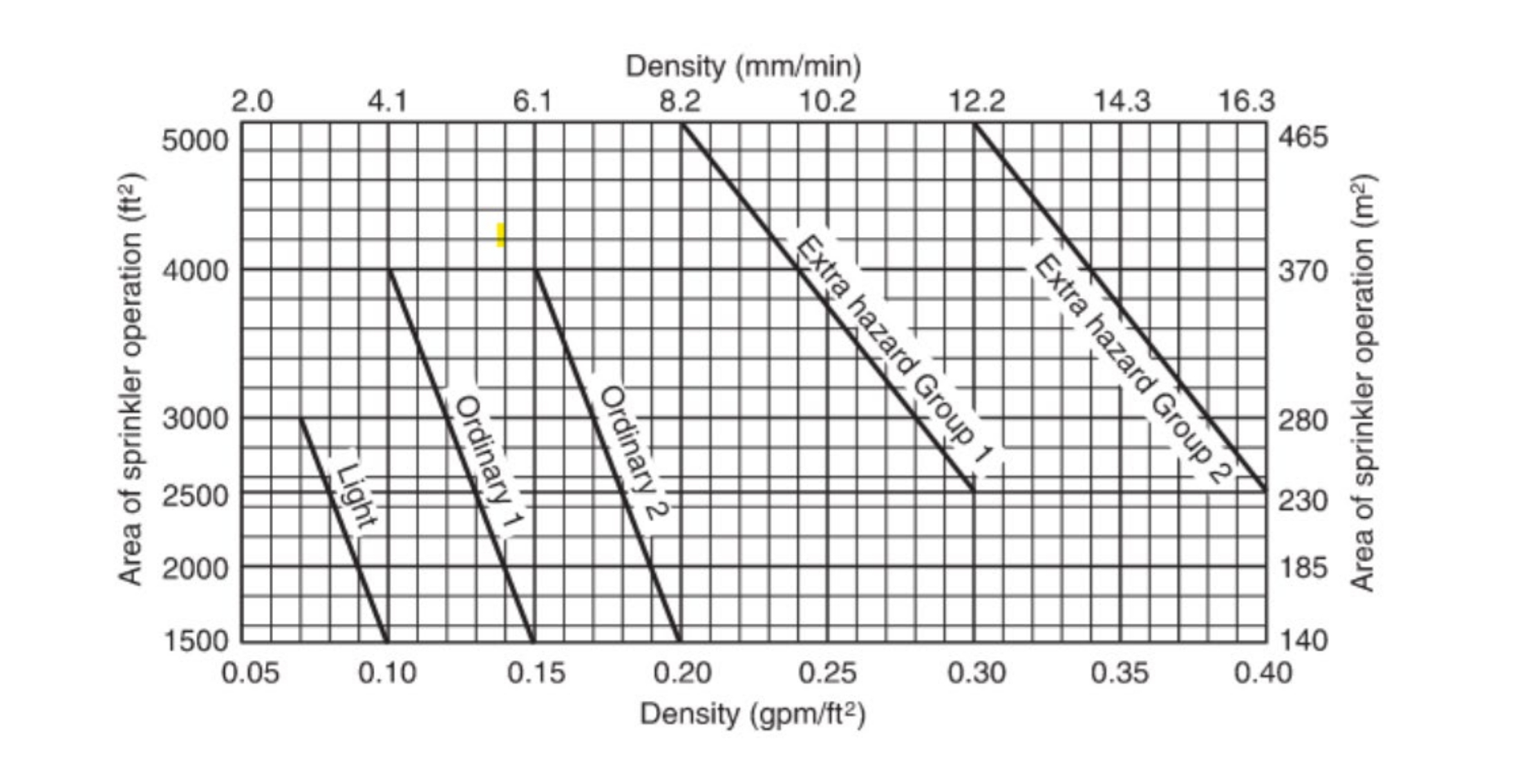
The water demand for the sprinklers is calculated per the density/area curves noted in NFPA 13, Section 19.3.3, based on the occupancy hazard classifications (light, ordinary or extra hazard (see Figure 19.3.3.1.1). A 30% increase in a remote area is considered in the calculations if a dry sprinkler system is used. The room design method and special design area calculations will be discussed in a separate article.
Sprinkler system hose demand in fully sprinklered buildings shall not be required to be added to standpipe calculations for combined systems as per NFPA 14-2019, Section 7.10.4.
For a combined system in a building equipped with partial automatic sprinkler protection, the standpipe flow rate required shall be increased by an amount equal to the hydraulically calculated sprinkler demand or 150 gpm for light hazard occupancies, or 500 gpm for ordinary hazard occupancies, whichever is less.
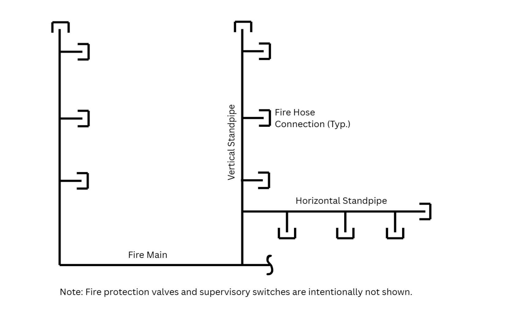
Vertical standpipe (Class I and III)
• First riser. The minimum flow rate for the hydraulically most remote standpipe riser is 500 gpm at the two most remote 2 1/2-inch fire hose connections as per NFPA 14-2019, Section 7.10.1.1.
• Additional risers. For floor areas that do not exceed 80,000 square feet, each additional standpipe adds 250 gpm to the demand.
• Maximum demand:
a. Sprinklered buildings. The maximum flow rate is capped at 1,000 gpm for buildings fully sprinklered in accordance with NFPA 13.
b. Partially sprinklered buildings. The calculated demand is generally capped at 1,250 gpm.
c. Note on local codes. For example, New Jersey Building Code, Section 905.2.1.2, allows a maximum flow of 1,250 gpm for combined fire standpipe and sprinkler systems.
Horizontal standpipe
Horizontal standpipe requires higher demand calculations to accommodate tactical fire department hose-line deployment.
• Flow rate. If a horizontal standpipe supplies three or more hose connections on any floor, the minimum flow rate will be 750 gpm.
• Logic. This configuration assumes three hose lines are being deployed simultaneously, unlike a vertical standpipe, which typically assumes two.
• Piping. These usually require a minimum of 4-inch pipe to meet the demand.
Determining pressure requirements
Once the flow rate is established, the pump must provide enough pressure to overcome gravity (static head) and friction while maintaining residual pressure at the outlet.
• Residual pressure minimum requirement. The system must maintain a specific residual pressure at the most remote hose connection. This is typically 65 psi for New Jersey and New York City, and 100 psi for New York state. As per New Jersey Building Code, Section 905.2.1, a residual pressure of 65 psi is not required in buildings equipped throughout with an automatic sprinkler system and also where the highest floor level is not more than 150 feet above the lowest level of fire department vehicle access.
• Maximum limit. The maximum pressure connected to hose valves at any point in the system cannot exceed 400 psi (per NFPA 14-2019). There could be high-pressure zones beyond 400 psi in the system as long as they are not connected to hose valves.
The calculation formula
To size the pump zone, you must calculate the total pump discharge pressure.
Total Pressure Required = Static Head + Residual Pressure + Friction Loss
• Static head. Calculate the vertical distance. For example, a 650-foot zone requires overcoming static pressure of 650 feet x 0.433 psi/foot = 281.45 psi.
• Friction loss. Use a Hazen-Williams friction loss calculator to determine loss through piping and fittings.
• Safety buffer. It is advised to include a buffer at a minimum of 10 psi to 20 psi to account for fluctuations in city water pressure; require further confirmation with the water utility company.
Building height and zoning strategies
Building height dictates whether a single fire pump is sufficient or if the building must be divided into zones. Engineers should consult local fire departments when determining fire pump zones based on the available fire pump for firefighting.
• High-rise building definition per the International Building Code. A high-rise is defined as a building where an occupiable story is greater than 75 feet above the lowest level of fire department vehicle access.
• Zoning for pressure management. Because the maximum pressure allowed in the system is 400 psi per NFPA 14-2019, up from 350 psi in previous versions, engineers can add more floors to a single fire pump zone.
• Optimization. Engineers should try to divide the building into equal zones while keeping the pressure under 400 psi to optimize fire pump size.
• Zone height. Based on a 65-psi residual requirement, a single zone can cover approximately 59 to 60 floors (a 10-foot average floor height) as a rule of thumb. If a 100 psi residual is required, the number of floors per zone will decrease.
For buildings exceeding 420 feet in height:
• Risers. Each sprinkler zone must be supplied by no fewer than two risers, as per International Building Code, Section 403.3.1.
• Water supply. As per the International Building Code, Section 403.3.2, fire pumps must be supplied by connections to at least two water mains located on different streets to ensure redundancy. If two different streets are unavailable, two separate connections may be made from the same street main, with an isolation valve between, pending confirmation from the water utility and the local fire department.
A jockey pump is typically sized at 1% flow of the fire pump, and the jockey pump head is typically 10 psi higher than the fire pump head. For example, a 1,000-gpm and 100-psi head fire pump will be piped with a 10-gpm and 110-psi jockey pump.
Sizing a fire pump is ultimately an exercise in aligning hydraulic performance with code-driven demand while maintaining reliability under real fire conditions. The fire protection engineer must first determine the governing flow — typically the standpipe demand in high-rise or complex buildings — ensuring that combined sprinkler and hose demands are correctly applied per NFPA 13, NFPA 14 and local amendments.
Once this flow is established, the required pump pressure is calculated by combining static head, friction losses and residual pressure, with an added safety margin to accommodate supply fluctuations and operational uncertainties.
Sahil Mahajan, PE, P.Eng., CPD, LEED Green Associate, is the plumbing and fire protection department head at KEA Engineers. He has nearly 20 years of experience in HVAC, plumbing and fire protection design and is a licensed professional engineer in the United States and Canada.


