
The old adage “out of sight, out of mind” may not be more apt than when it pertains to the underground pipe network between a water source and the in-building fire protection system it serves.
Code officials spend many hours inspecting and witnessing inspections and tests on water-based fire suppression systems such as sprinklers, fire pumps and standpipes, but usually get only one chance to review and approve the incoming supply lines before they are buried forever.
The underground arrangement of pipe, valve and fittings is an essential part of fire suppression system performance. The National Fire Protection Association (NFPA) design and installation standards — adopted and enforced by the International Building (IBC) and International Fire (IFC) codes — generally require water-based systems to have one “reliable” means of supply and, in many cases, the lines between the water purveyor and the fire protection system fulfill that role.
Designers and code officials need to take time to review NFPA 24: Standard for the Installation of Private Fire Service Mains and Their Appurtenances that is the primary guide for specifying materials, pipe sizes, pipe and valve configurations, installation requirements and testing. NFPA 25: Standard for the Inspection, Testing and Maintenance of Water-Based Fire Protection Systems includes requirements for regular maintenance on private water service mains. Both documents are adopted by reference in the IFC making them enforceable by the local code official.
Public or private?
In some jurisdictions, the municipal water purveyor supplies the underground main to the point where it connects to the fire protection system near or inside the building. Others may stop at the property line, backflow prevention device (if required), or other clearly demarcated point that establishes clear separation between public and private ownership.
For the purposes of applying NFPA 24, the standard takes a slightly different approach, by defining a “private fire service main” as…
. . . that pipe and its appurtenances on private property (1) between a source of water and the base of the system riser for water-based fire protection systems, (2) between a source of water and inlets to foam-making systems, (3) between a source of water and the base elbow of private hydrants or monitor nozzles, and [sic] (4) used as fire pump suction and discharge piping, (5) beginning at the inlet side of the check valve on a gravity or pressure tank.
Regardless if the system is installed and maintained by the municipality, once it crosses the property onto the project site it falls under the regulatory influence of NFPA 24. Some states license or certify underground installation contractors to help assure their work complies with national standards and local requirements. The licensure helps code officials feel confident in the systems’ reliability.
Material requirements
A second element to enhance reliability is the NFPA 24 requirement that underground pipe or tube is listed for fire protection service and complies with one of many industry standards for the materials. Table 1 provides a sample of a few of these material standards and the pipe size ranges to which they apply. Steel pipe is not permitted unless specifically listed for fire protection service.
Table 1
Materials Suitable for Underground Water Mains for Fire Protection Systems
(Examples)
|
Material |
Standard(s) |
Diameters |
|
|
|
|
(inches) |
(mm) |
|
Ductile iron |
AWWA C 104, C 105, C110, C 115, et. al. |
3-48 |
76.2 – 1 219.2 |
|
Steel |
AWWA C200, C203, C 205, C 206, et. al. |
6-144 |
152.4 – 3 657.6 |
|
Concrete |
AWWA C300, C301, C302, C303 |
|
|
|
Asbestos concrete |
AWWA C400, C401 |
4-16 |
101.6 - 406.4 |
|
Plastic |
AWWA C900, C906 |
4-63 |
101.6 – 1 600.2 |
|
Copper |
ASTM B75, B88, B 251 |
|
|
The pipe type and class for any specific application should be selected by the design engineer based on maximum system working pressure, pipe installation depth, soil and corrosion conditions and the pipes’ ability to resist external loads such as earth loads, installation beneath buildings (generally discouraged but allowed in certain conditions) and traffic or other vehicle loads that may be imposed on the pipe.
Pipe sizes should be based on the anticipated fire protection demand, including influences of daily and seasonal industrial and domestic demand, possible interruption by flooding or freezing, and — perhaps most important — the potential impact of future demands on the supply. As communities grow outward from their core utility sources, the quality of the water pressure and flow often deteriorate unless steps are taken to address added development. The lessening of pressure and volume over time that might result in a fire protection system being unable to perform as it was designed is a very real and concerning problem that could open the water provider to legal action. Pipe sizes smaller that 6 inches in diameter should never be used to supply fire department hydrant systems. They should be discouraged in all other circumstances.
Installation factors
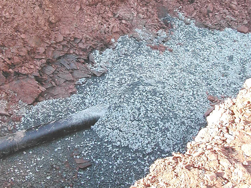
Since the underground pipe may never see the light of day after installation, great care should be taken when it is installed.
Pipe, valves, hydrants, gaskets and fittings should be inspected when they arrive on the jobsite or just prior to installation. Once laid, exposed pipe ends should be plugged or otherwise covered to prevent dirt, rocks and other debris getting into the supply line.
Depending upon climate and geographical conditions, underground water lines should be installed at least 1 foot beneath the local frost line, and if frost is not an issue, at least 2 ½-feet beneath the finish grade to protect the pipe from physical damage. Pipe that is run under driveways should be covered at least 3 feet and if run under railroad lines, at least 4 feet. Running pipe beneath buildings is discouraged because of the potential for settlement onto the pipe, but if necessary it may be run under arched foundations or in covered trenches with isolation valves installed at points where the pipe runs under buildings.
When backfilling over the pipe, the clean fill should be tamped or puddled around pipes to prevent settlement or lateral movement. Rocks should be avoided in trenches because normal dynamic forces could result in damage or leaks.
Underground acceptance tests
The underground water line between the municipal source and fire protection system (or backflow prevention device, if mandated) requires two important tests outlined in NFPA 24. The first is a hydrostatic pressure test and the second is a flush to assure there is no residual debris in the pipe before connecting it to the fire protection system.
Once laid in the trench and supported or anchored to prevent movement, underground pipe must undergo hydrostatic pressure test at a gauge pressure of 200 psi (13.78 bar) or 50 psi (3.44 bar) in excess of the system working pressure, whichever is greater. (If, for example, the incoming water pressure were 183 psi [12.6 bar], the underground pipe would have to be tested to 233 psi [16.06 bar].) The test pressure must be maintained at gauge pressure of ±5 psi for two hours. If there is no visible leakage or the gauge pressure loses less than 5 psi (0.345 bar), the test is considered successful.
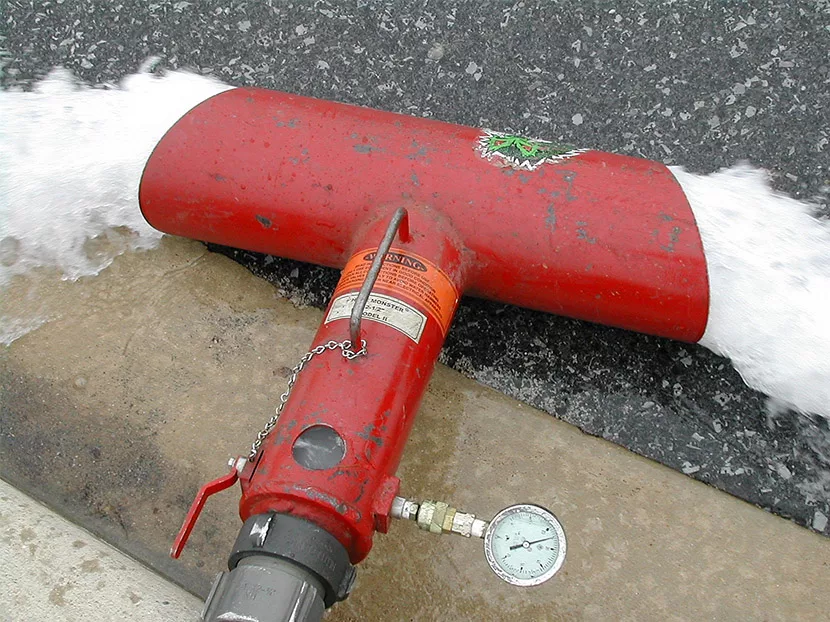
Underground piping, from the water supply to the system riser, and lead-in connections to the system riser also must be completely flushed at a rate of not less than 10 feet per second (3.04 mps) before the connection is made to downstream fire protection system piping (see Table 2). The flushing operation must continue until water flow is verified to be clear of debris.
Table 2
Flow Required to Produce Velocity of 10 ft/sec in Pipes
|
Nominal Pipe Size |
Flow Rate
|
||
|
in |
mm |
gpm |
lpm |
|
2 |
50.8 |
100 |
378.5 |
|
2 ½ |
63.5 |
150 |
567.8 |
|
3 |
76.2 |
220 |
832.8 |
|
4 |
101.6 |
390 |
1 476.3 |
|
5 |
127 |
610 |
2 309.1 |
|
6 |
152.4 |
880 |
3 331.2 |
|
8 |
203.2 |
1,560 |
5 905.2 |
|
10 |
254 |
2,440 |
9 236.4 |
|
12 |
304.8 |
3,525 |
13 343.6 |
Source: NFPA 24: Standard for the Installation of Private Fire Service Mains and Their Appurtenances, 2016 Edition
If a backflow prevention assembly is installed in the supply line to isolate the fire protection system from the potable water source, the device must be “forward flow” tested to ensure proper operation.
Documentation
There’s an old fire service adage that “the job ain’t done until the paperwork’s finished.” This is equally true for acceptance testing fire protection systems. The IBC, IFC and all of the NFPA documents mentioned in this article require the various tests are properly documented to show they have been completed and meet the requirements of the codes and standards. The International codes also require a “statement of compliance” that the installing contractor attests the system has been installed in accordance with the approved plans, manufacturer’s equipment requirements and appropriate national standard. Any deviations from these must be included in the report.
The NFPA documents include model reporting forms, and some fire or building code officials may be able to provide forms that satisfy their requirements.
Summary
The underground water systems that support aboveground fire protection systems are integral to successful outcomes in the event of a fire. Designers, installing contractors and code officials must pay close attention to the details of these installations because once they are buried they may never been seen again until something goes wrong — and no one wants that!


