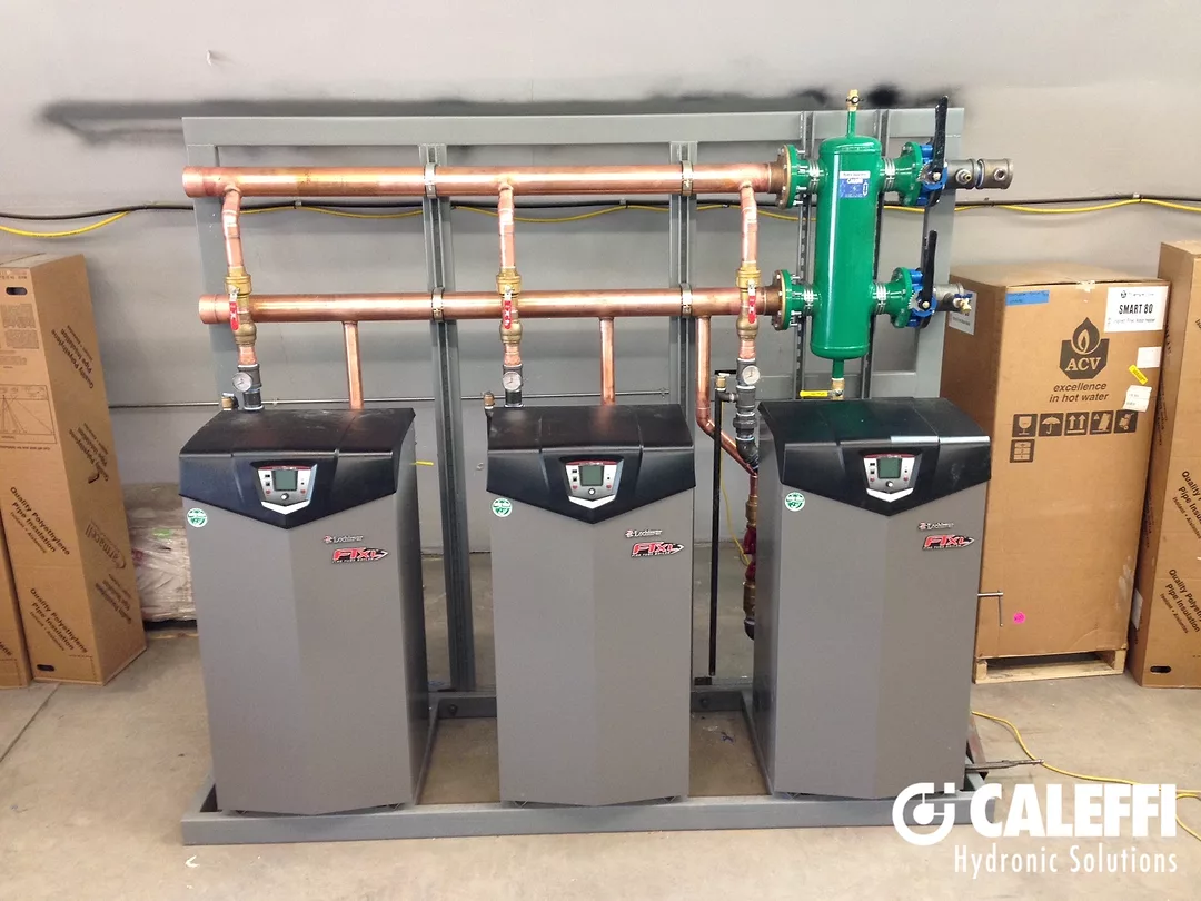
It’s not uncommon to see multiple boilers piped together on certain jobs (see Figure 1). You may be trying to accomplish a number of things by doing this. Typically, you’ll need multiple boilers to cover the heat loss, but it may be cheaper to have multiple small boilers instead of one big one.
It’s also common for redundancy in those mission-critical applications. In fact, it’s become so common that many boiler manufacturers include the ability to operate multiple boilers right in their controls without extra hardware.
Another reason for multiple heat sources coming around the corner isn’t so common at this point. With fossil fuels on the chopping block, there’s a good chance your favorite boiler may be replaced with something a little more exotic, green and full of refrigerant.
Ground- and air-source heat pumps have been around a long time, but are marching to the frontlines of hydronic heating design. While they’re a logical next step towards carbon-neutral buildings, they’re not without their obstacles — the biggest being their ability to cover the heat loss on a design day.
Covering the heat loss isn’t a problem for a properly sized ground-source heat pump system as it has a more consistent heat source. However, I’ve seen intentionally undersized loop fields as the juice wasn’t worth squeezing since you could have a supplemental heat source (electric resistance, gas boiler, etc.) for those few design days of the year. This may seem counterintuitive, but it’s likely still more cost-effective to operate compared to an all-fossil-fuel option.
We’ve also seen air-source heat pumps making headway in the North American hydronic heating market. They’re an alternative to ground-source units without the loop fields, but are dependent on the inconsistent outdoor air temperatures as a heat source. Heating output from these air-source systems at low ambient temperatures is getting better all the time. However, similar to geothermal, it may not make sense to size the unit based on a design day.
Sizing to cover the whole load may not be possible due to the electrical requirements of the equipment. Return on investment may also be a constraint as the cost to add another loop or ton may take decades to recoup versus other options. This is where a backup or a supplemental heat source is going to become increasingly prevalent.
With that in mind, different piping configurations and controls can make or break your system’s performance and your customer’s expectations.
Piping for performance
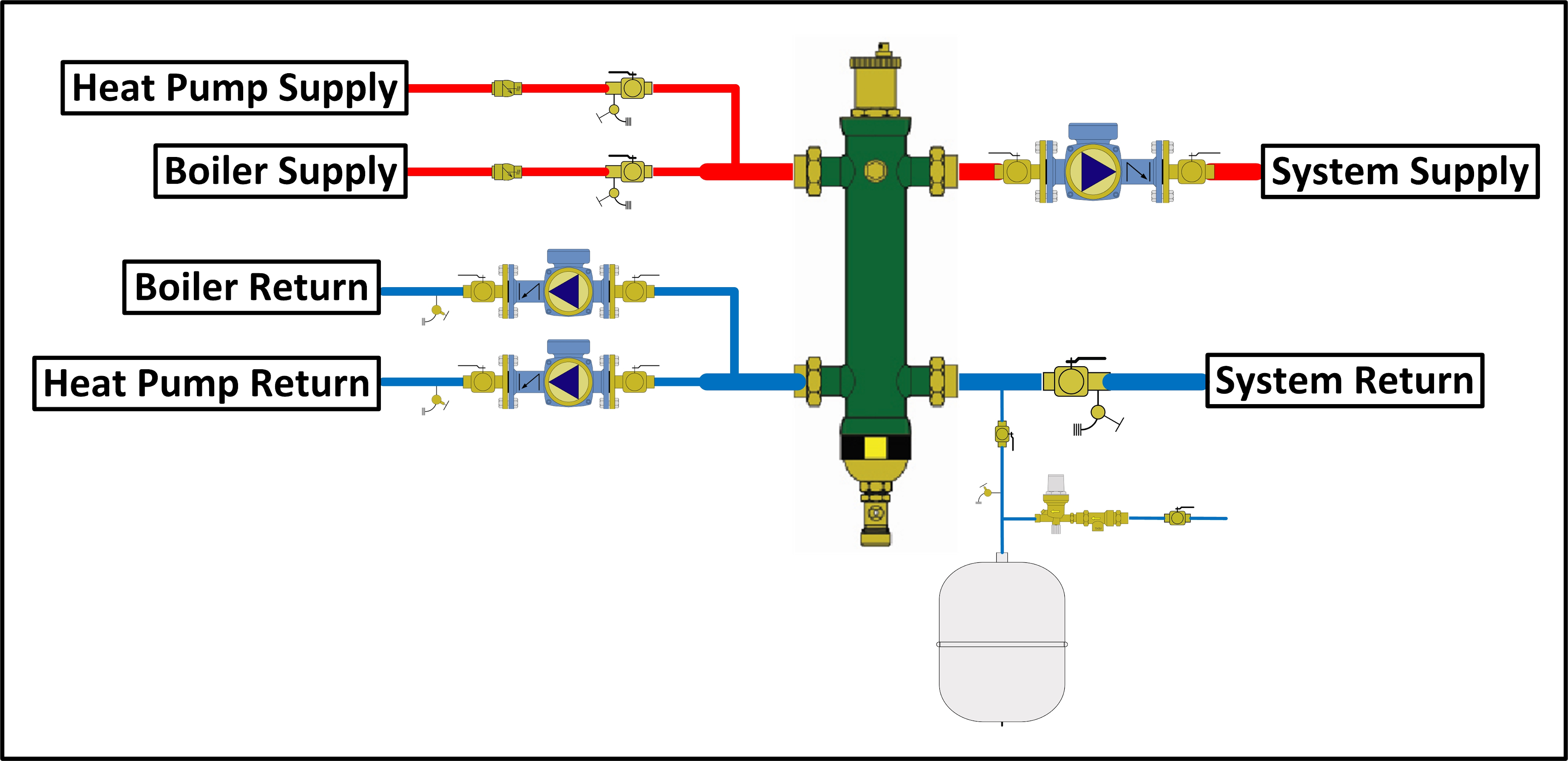
The first piping arrangement (see Figure 1) is pretty standard: piping multiple heat sources to a single form of hydraulic separation using the same supply and return headers. Typical choices in hydraulic separation include closely spaced tees and low-loss headers (hydraulic separators). This option works well if you have similar heat sources, such as two high-efficiency gas boilers. The boilers can operate independently or work together and can be set up as cold start due to their low mass and fast recovery.
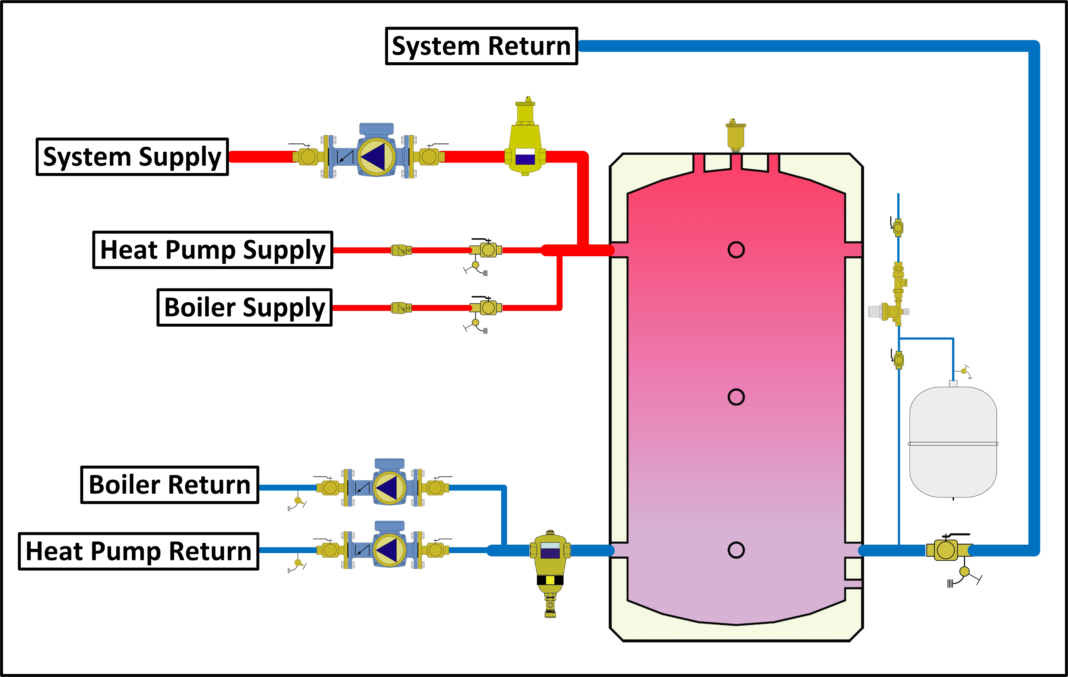
When using a heat pump in conjunction with a backup boiler (fossil fuel or electric resistance), I would suggest switching out the close tees or low-loss header for a buffer tank (see Figure 2). The added mass of a buffer tank acts as a storage battery and can help to offset the slower recovery times of a heat pump. This is especially important when using low-mass heat emitters such as panel radiators.

With a fast-reacting heat emitter, it’s important to have heat at the ready. The buffer tank also allows for a more advantageous control strategy with the use of a multistage setpoint control operating the heat sources from a sensor in the tank and not as a cold start heat source initiated by a thermostat in the living space.
You’ll also notice a slightly different way of piping a traditional buffer tank. Instead of a typical four-pipe configuration, a three-pipe option is used. Through this method, you have the benefits of a buffer tank while allowing heat to go directly from the heat source to the load without having to pass through the buffer tank. The benefit of this is quicker recovery with the panel radiators noted previously.
It also lets the system circulator pull from the buffer tank when the sensor for the setpoint control in the tank is satisfied and the heat sources are off.
There’s also opportunity in certain applications, such as warehouses, to ditch the buffer tank and trade it for a slab of concrete and in-floor tubing. This concrete and its thermal capabilities are not as quick to react to a call for heat, but it’s also not as quick to give up all its heat when a door is opened.
Think of it like that train you waited patiently for at a crossing while on your way to your next appointment. It may have been going 20 mph as it passed, but how long did it take to get going that fast? How long would it take to slow down to a stop? High-mass heating systems are similar to that seemingly never-ending train.
Even with a large slab, you will still require hydraulic separation but without the added mass from a buffer tank (see Figure 3). With the lower delta T and higher flow rate requirements of a heat pump, the flow demands of your load likely won’t match. Hydraulic separation allows these flow rates to differ without conflict. A multistage setpoint control with outdoor reset could be used in this scenario with continuous flow in the slab and the sensor on the system supply pipe.

Logical controls
Controlling multiple heat sources is another task requiring as much, if not more, attention than piping. There are a number of ways to do this via aftermarket controls and even controls built into heat pumps. In order to maintain a comfortable space, these controls need the logic to start, stop and transition from one heat source to the other. This is usually done because the air-source heat pump isn’t keeping up due to high recovery demand or decreased output due to low ambient.
Another reason to turn off the air-source heat pump in this configuration is that it’s not cost-effective to run. If your supplemental/backup heat source is an electric boiler, it will have a coefficient of performance of 1. Chances are, your heat pump will still be able to beat that even in low ambient conditions.
However, if your backup heat source is using a fossil fuel, there may be a point in the operation of your heat pump where it’s just cheaper to run the gas boiler. This point is a moving target based on the potentially volatile cost of fuel or electricity. Websites can help compare different fuel types based on cost and equipment efficiency. I highly suggest checking them out (one such site is at https://bit.ly/3PiNqZx).
Ultimately, there are a lot of ways to accomplish what is needed of your system, and while it may not be on your plate for tomorrow, it’s certainly coming. I encourage everyone to get a bit more comfortable with piping and controlling multiple heat sources. As an industry, we need to see this “problem” as an opportunity to grow our skillsets and offer more solutions for our customers.


