
Hydraulic separation is an effective way to prevent conflicts between circulators that share common piping. This common piping could include a typical header, but it could also consist of your heat source. For the most part, when we talk about hydraulic separation, our biggest concern is the boiler and distribution circulators. We want to ensure that these two (or more) circulators are unaffected by the others during operation.
While typically referred to as hydraulic separation, you may also have heard it called primary/secondary and even decoupling. All are synonymous with the task that you’re trying to accomplish. Not so long ago, this task wasn’t even thought of, as we had boilers and heat emitters with free-flowing, wide-open water paths. Ironically, this may have been the pinnacle of hydraulic separation, and we didn’t even realize it!
Today, however, we have boilers with tight passageways, lower water volume and pressure drops that would’ve seemed crazy in years past. You’ll also find that most modern boilers include minimum flow requirements and when not met, make them a little cranky due to short-cycling and overheating.
Hydraulic separation allows you to properly size a circulator for your boiler and distribution systems. It also helps to deal with any imbalance in flow rates. It can be accomplished with closely spaced tees, buffer tanks and hydraulic separators. For the sake of this conversation, we’re going to focus on the finer points of hydraulic separators.
Sizing the separator
The first detail to consider is sizing. This may come as a surprise, but it’s not always based on pipe size! Just like mix valves, zone valves and various other components in a hydronic heating system, these are sized based on flow rate. What you need to remember is that it’s based on whichever is higher: the boiler or the distribution side flow. Most manufacturers have recommended flow rates for the various sizes in their offerings.
These recommendations are based on the possible flow rate through the barrel and the corresponding velocity and pressure drop. Higher velocities and pressure drops can lead to unwanted flow being induced from one side of the hydraulic separator to the other. This is why you’ll typically see the barrel of a hydraulic separator 2.5 to 3 times the diameter of the pipe connected to it.
The good news is that you cannot oversize a hydraulic separator. It’s one of the few items in hydronic systems that we can oversize without undesirable consequences! This rule also applies to coalescing-style air separators and dirt separators. However, when undersized, any flow imbalance that must traverse the barrel will find it more difficult to pass through and may decide to go somewhere it shouldn’t.
Proper piping prevents poor performance
Hot on top, cold on bottom — boiler on one side, system on the other. This is the basic rule for piping hydraulic separators, as shown in Figure 1. We want the supply from the boiler and the supply to the system on the top connections. Because most hydraulic separators have an air vent at the top, it’s advantageous to have the hottest water travel across the top. Gases are less soluble in water as water temperature increases, and the low velocity in the barrel will allow air to rise and quickly exit your system.
 This leaves the return from the system and the return to the boiler connected to the bottom of the separator. Again, the low-velocity barrel will do its magic by letting any debris returning from your system drop to the bottom of the hydraulic separator, where there will always be a drain so you can do a blowdown on regular maintenance. How often should you be doing blowdowns? That will depend on how dirty your system is!
If you’re not going to follow this simple rule, you’ll still have hydraulic separation, but you won’t see the full benefits of air and dirt removal. If you were to put the supply (hot) across the bottom, any air bubbles would need to make their way to the top of the barrel and out the air vent. The problem is that some of those air bubbles can hitch a ride from the flow across the top and get sent right back into your system. I’ll bet you can imagine what happens with debris if the return (cold) is piped across the top.
My personal favorite when it comes to creative hydraulic separator piping is what I call the “crisscross applesauce” and it’s just as amazing as you’d think. In this scenario, the supply (hot) is piped to the top connection of one side, while the other side is piped to the bottom. The returns then suffer the same fate (see Figure 2).
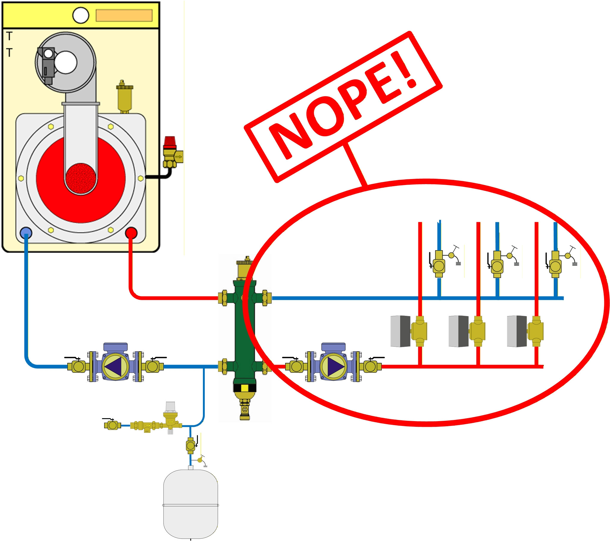
As before, you’ll still be hydraulically separated, but now you have a big problem with the fact that the supply (hot) and return (cold) are going to be mixing in the barrel. This will lower the supply water temperatures to the heat emitters and raise the return water temperatures to the boiler. This is less than desirable, given the reduced heating capabilities from the emitters and reduced efficiency from the boiler, so let’s not do that!
On top of all that, you’ll want to be sure to “pump away” from the hydraulic separator. This term, made famous by Dan Holohan, was definitely referring to pumping away from the expansion tank, and it serves you well to abide by it when piping a hydraulic separator. This will keep pressure lower in the separator, making it even easier to remove air and ensuring that none of the debris from your system passes through a circulator before the separator.
Careful where you put that thing!
Along with proper piping of the hydraulic separator, you’ll need to make sure the accessories are also in the right place. As noted previously, you’ll hopefully be pumping away from the hydraulic separator. This would make it a great place to connect the fill valve and expansion tank. Many contractors will recognize this and also see the connection at the bottom of the separator.
While convenient, the bottom connection on the separator, where the drain resides, is probably the worst place to install the fill valve and expansion tank (see Figure 3). We’re talking about a device that’s going to catch debris and if you park the fill valve and expansion tank under it, you’ll have two problems.
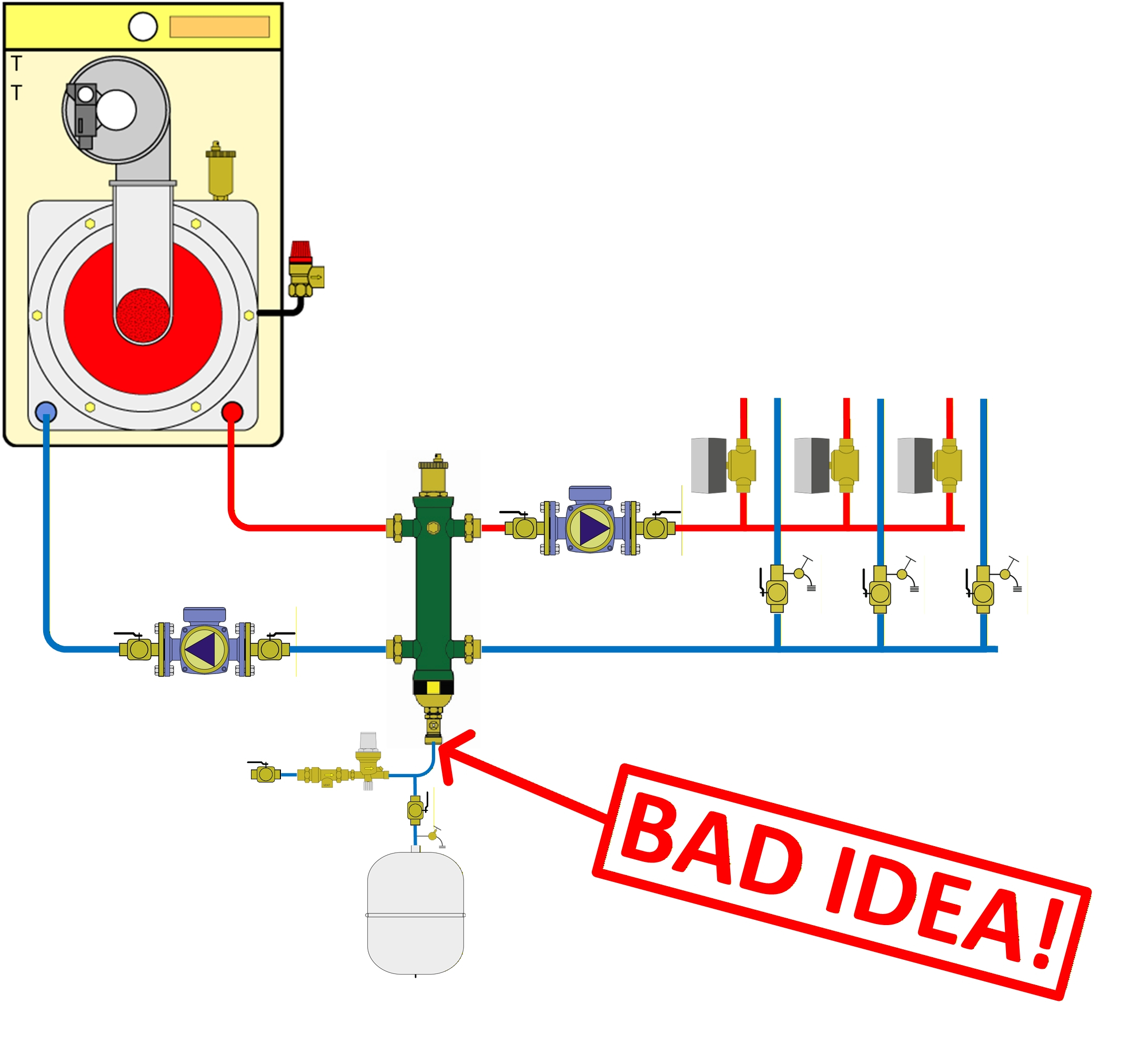
The first is that dirt and debris will fall to the bottom and sit on top of the expansion tank diaphragm. The second is that if the fill valve is required to do its job, you’ll stir up debris in the bottom of the separator and likely send it back into your system.
The best place, despite having to add a fitting, is any of the supply and return connections directly adjacent to the hydraulic separator. Typically, you’ll have more room and flexibility on the return at the bottom, but I’ll leave that up to you!
What you’ll come to realize is that hydraulic separators can do a lot for you and your hydronic systems. This is, of course, dependent on proper design and installation, just like anything else in your heating system!