A domestic water system is a crucial part of every building. It provides the needed water for consumption, hand washing, process water, and more. However, like others, it’s a system of the building infrastructure that can be taken for granted. When you use a drinking fountain, turn on a faucet to wash your hands or run a piece of sterilization equipment, you expect the water to be there.
Good design and proper installation won’t give the user a reason to question where the water is coming from or what it takes to get it there.
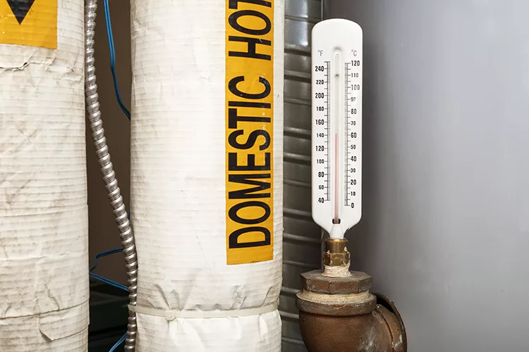
You could argue that domestic hot water is the most critical part of the overall domestic water system. It needs to be provided at the right temperature and within a reasonable amount of time for user comfort. The longer a user must wait for hot water at the faucet or other fixture, the more water is wasted down the drain. This also wastes the energy used to heat the water initially.
To provide hot water to the fixtures in a timely manner while also minimizing waste and energy inefficiency, a circulation or return system is needed. The intent of a hot water circulation system is to flow enough water through the piping to maintain a set temperature. By keeping the water at the desired temperature, there is less waste when the fixture is used. Because the circulated water is returned to the water heater(s) to replenish the supply, the energy used to heat that water is not lost.
Early in my career, when I was taught how to design a hot water return system, it seemed the consensus was to rely on rules of thumb to determine the circulation pump selection and pipe sizing. Throughout my years in the industry, I have witnessed many competent plumbing engineers and designers use those same rules of thumb in their designs.
Typically, that includes assigning 0.5 gallons/minute (gpm) for each average-length return branch circuit, and possibly 0.75 or 1 gpm for each longer or bigger circuit. Then, by adding those flow rate values up for each circuit, the design flow rate for the circulation pump is determined.
Perhaps it’s because of the way my brain works, but I always thought this was an oversimplified approach. I didn’t like relying solely on rules of thumb that couldn’t be backed up with calculations or real-world observations. While I think this method is a quick way to get in the ballpark with a pump selection, it is almost always oversized, based on my experience.
I developed a calculation-based strategy that considers the actual heat loss in the piping based on the size of the pipe and insulation thickness. To be clear, I didn’t invent this strategy I’m going to share with you. I reviewed and borrowed different approaches from publications and textbooks. I put them together and tweaked them to create a design strategy that made sense to me.
This strategy helps me to accurately size the circulation pump and the return water piping, providing the confidence of a design backed up with calculations.
Step 1: Information gathering
Gather and tabulate all the physical attributes of the piping system and the design parameters you will use. This will help determine the critical factor, which is the heat loss per lineal foot of pipe.
Create a spreadsheet with a table for the following attributes of your system:
Nominal pipe sizes
Actual outside diameter of the pipe
Actual inside diameter of the pipe
Insulation thickness for each pipe size
Hot water delivery temperature
Expected indoor ambient air temperature
The delta T of the hot water system (At what temperature will the hot water return to the water heating source?)
Heat loss per lineal foot of pipe for each pipe size in BTU/hour-foot (hr-ft)
This is accomplished using the following equation:

Q = BTU/hr-ft
k = thermal conductivity of insulation (BTU-in/hr-ft2-°F
(The insulation manufacturer’s product information will
tell you this.)
ΔT = temperature difference between the water and
ambient air (°F)
Do = outside diameter of insulation (OD of bare pipe +
insulation thickness x 2) (inches)
Di = outside diameter of bare pipe (inches)

Step 2: Flow rate
Calculate the required circulation flow rate for all parts of the circulating piping and the total system flow rate using the information from Step 1. I prefer to break the system into hot water “mains” and “circuits.” Anything with a balancing valve is a circuit. A pipe with multiple circuits connecting into it is a main.
I create separate tabs in my spreadsheet, one for the mains and one for the circuits. Keeping them separate helps in a later step. Tabulate the lengths and sizes of hot water piping that are a part of each circuit or main. Using the calculation for Q in Step 1 will give a heat loss for each length of pipe. Adding these together will give the total expected heat loss in the hot water piping of the circuit or main.
Multiply that value by two-thirds to estimate the heat loss in the associated circulation piping of the circuit or main. Adding those two values together gives the total expected heat loss of the circuit or main. While two-thirds is an estimate, I find it only adds tediousness in calculating the exact heat loss of the circulation piping, together with the hot water piping. I have found that this estimation does not contribute to a less accurate overall calculation.
With the total heat loss, convert to a flow rate by using the equation:

This flow rate in gpm is the amount of flow required in the circuit or main to overcome the expected heat losses in the pipe and maintain temperature. By laying out the hot water system and doing this calculation for each circuit and main, you can determine the flow rate required at each balancing valve. Adding these calculated flow rates together will give the total required flow rate for the circulation pump.

Step 3: Discharge head
Determine the circulation pump head. Choose a value for the allowable uniform friction head loss in the circulation piping. I usually stick with 2ft hd/100ft, but it can be any reasonable value that doesn’t produce excessive velocities. Find out what the distance from the pump location to the farthest circuit or end of the piping network is. Use this equation to determine the circulation pump head.

You can now select a circulation pump using the flow rate in Step 2 and the discharge head in Step 3.
Step 4: Size the piping
Size the circulation piping network. I use the following equation taken from a book published by the American Society of Plumbing Engineers called “Engineered Plumbing Design II” by Alfred Steele and revised by A. Calvin Laws.

q = flow rate (gpm)
d = actual internal diameter of pipe (inches)
h = total head available for friction loss or pump head
(ft hd)
L = equivalent length of run (feet)
This equation shows what the maximum flow rate is in each pipe size before exceeding the desired uniform friction head loss that the pump is sized for.
With this information tabulated, you can size the entire circulation piping system. Work your way from the farthest circuit all the way back to the pump, adding up the flow rates for each circuit and section of main. You’ll know it’s correct when you end up with the same gpm value as the pump flow rate in Step 2.
In my opinion, the best hot water return systems include a variable-speed pump and thermostatically actuated balancing valves. Using these components in conjunction with each other provides a highly efficient system. While the pump remains constantly running, it will fluctuate speed based on the demand. This creates energy efficiency. This type of balancing valve also eliminates the laborious nature of traditional manual balancing.
The system will automatically balance itself because each balancing valve operates locally and independently. They don’t have to be set to operate at a certain gpm corresponding to a constant-speed pump selection. This topic, the different technologies and their pros and cons, is a separate discussion that I won’t cover here. You can find great articles that tackle this topic in this publication and others. I encourage you to research those if you want to know more.

By going through this design process, you can have confidence in an accurately sized hot water return system based on calculations instead of rules of thumb. This was somewhat of a high-level overview and explanation. If you try it out, you may have tweaks of your own that fit your way of thinking.
I encourage you to build your strategy using this information as your framework. Our industry continually strives to produce efficient, thoughtful designs. We try to learn, grow and improve in every aspect of our discipline. Why should this be any different?
Ray Schwalbe, PE, ASSE 6060, is a mechanical engineer at HGA in Milwaukee. He has more than 10 years of experience specializing in plumbing, medical gas and specialty gas design for multiple market sectors, including healthcare, science and technology, corporate and higher education.


