
How oversized are sanitary drains in buildings? When the drainage fixture unit was introduced in 1928 for a methodological solution to convert plumbing fixture quantities to minimum required drain diameters, 5 gallons/flush (gpf) water closets were the norm.
Should something about the way drainage and vent piping is designed have fundamentally changed now that much of the world is using 1.28 gpf (4.8 liter) water closets? Should there be concerns about not having enough drainage flow to move solids? These are questions the plumbing engineering and code development community have been asking for decades.
To start answering these questions, it’s important to revisit the fundamentals of sanitary drainage theory: transporting water and solids to a point of discharge without creating pressure conditions within the drain that allow sewer gas to breach water seal barriers at fixture traps. In most of the world, a minimum of 2 inches (50 mm) of water is contained within a trap — a barrier so easily broken that it can be done with the human breath (2 inches is about a quarter the length of a typical drinking straw).
To avoid subjecting the drainage system to these pressures, it’s critical to ensure that drains do not flow too close to full, which will restrict airflow and create pneumatic conditions within the piping.
Filling heights in various standards
Concerns about solid deposition date back to the Victorian era. Edwin Chadwick’s “Report on the Sanitary Condition of the Labouring Population of Great Britain” from 1843 included some discussion from a London district surgeon who fixed a broom to the water closet (WC) lever to ensure continuous flow in the building drain and sewer. Inline flushing siphon tanks were suggested in the mid-19th century, and concepts of these devices continued to develop well into the later 20th century.
An example of a product developed in Scandinavia in the 1970s is the Gustavsberg siphon tank (later known as the WISA booster), which accumulates 4.75 gallons (18 liter) of drainage from fixtures before filling to a level that activates a siphon and provides a burst of flow. This was part of a strategy to overcome the comparatively lower drainage flow characteristics of the newly developed 0.8 gpf (3 liter) WCs.1
When compared with standards used outside of the United States and Canada, both the International Plumbing Code (IPC) and the Uniform Plumbing Code (UPC), which share sanitary drainage theory from the National Institute of Standards and Technology’s work in the first half of the 20th century, require larger drain diameters, more vent piping and lower filling heights, despite the U.S. having very water-efficient fixtures.
The United States and many European standards were developed around the theory of maintaining no more than 50% of the filling height. In China (GB 50015, Standard for design of building water supply and drainage) and the Netherlands (NEN 3215, Drainage system inside buildings - Requirements and determination methods), national standards assume no more than 60% and 70%, respectively, and the UK approved Document H from the 2010 Building Regulations allows even more.
Higher cross-sectional filling heights have the advantage of better carriage of solids, which is the other critical design element.
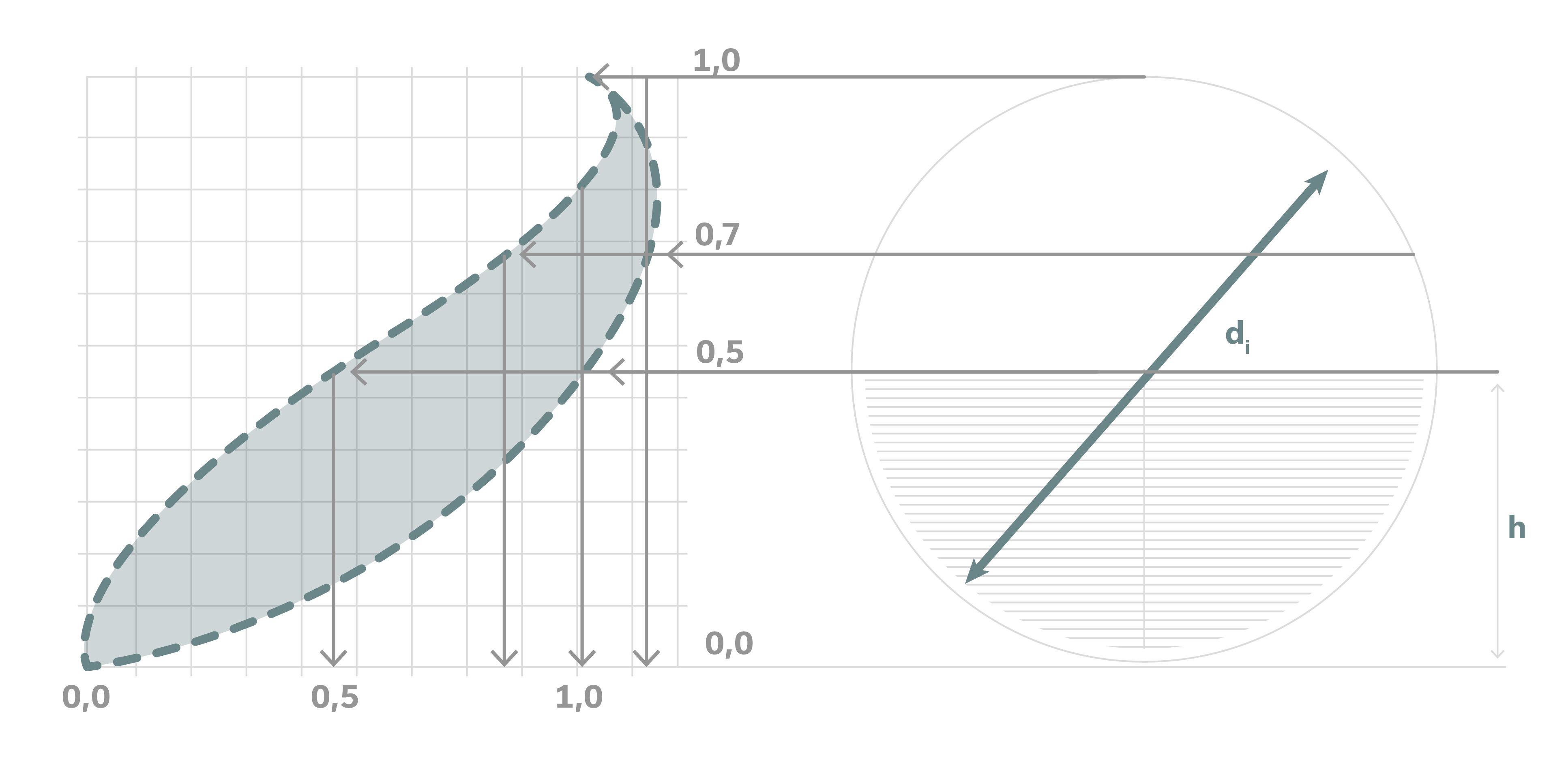
When applying the Colebrook White formula to horizontal drains, it is easy to see that the maximum velocity occurs near 80% (Figure 1). Higher-filling heights also help counteract the fact that the methods used for estimating flow in drainage design standards are very dated and don’t reflect realistic flow rates.
Level invert junctions, which are prohibited in standard AS/NZS 3500, Plumbing and drainage, used in Australia and New Zealand, reduce the filling height in horizontal drains as the water “spills” into branches as it moves down the drain (Figure 2), creating conditions for blockages to form. This style junction is currently allowed in the IPC and UPC, including in buildings with greywater diversion, where the WC drainage is particularly at risk for solid deposition.

A growing number of U.S. localities are also requiring water recycling, which is typically accomplished with a separate network for water closets from other fixtures, further deviating from the original considerations of NIST’s foundational work. This all points to the significant overdesign of U.S. drainage and vent systems, leading to expensive systems that, in many cases, perform worse.
Shallow flow and drainage performance
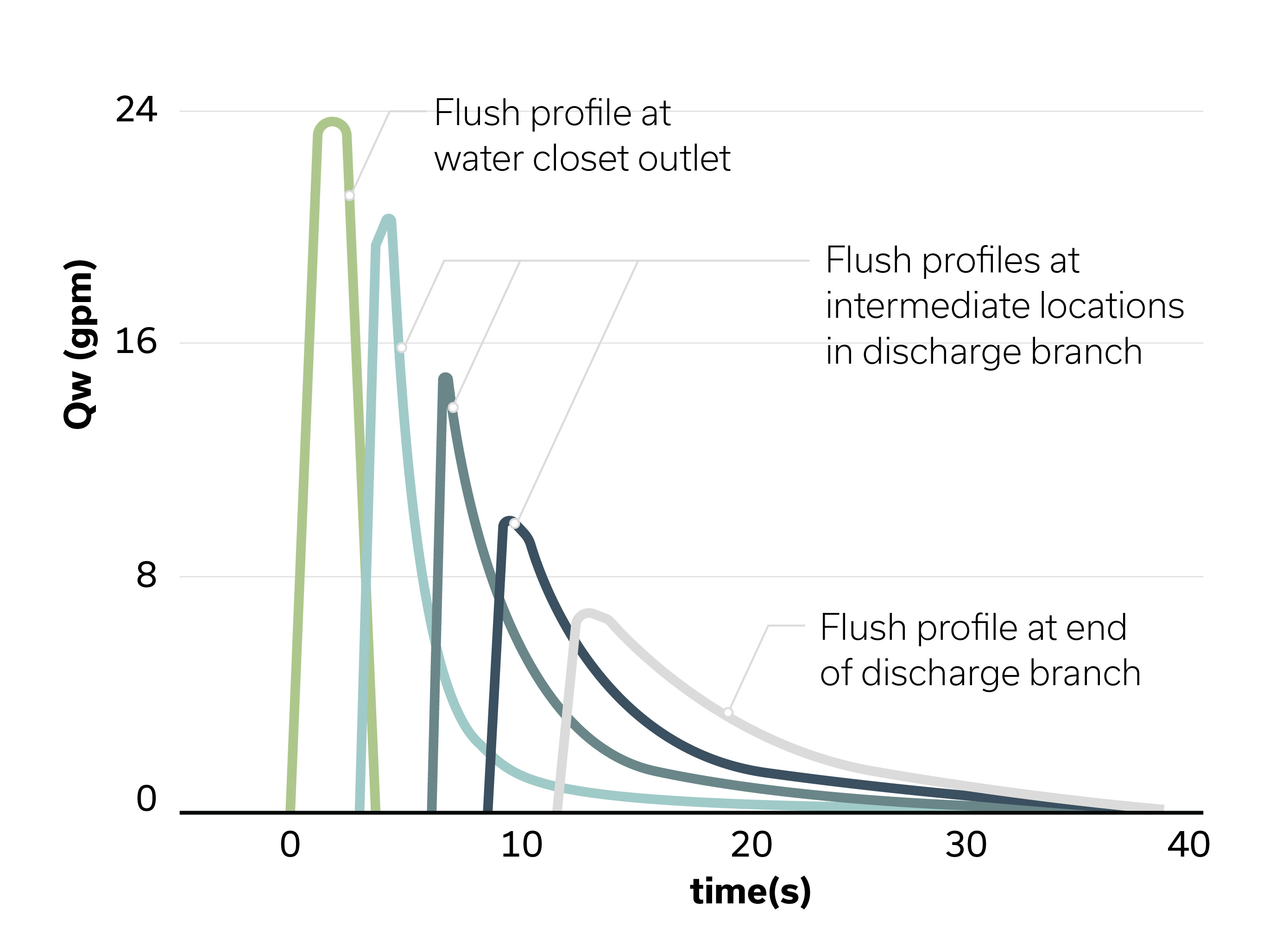
The height and velocity of unsteady flows, which describe the flow characteristics of the water closet, dissipate as the flow travels away from where the volume of water was released. Steady flows, such as those from a shower or a running faucet, will maintain a more predictable filling height along a long, horizontal drain. When a water closet is flushed, the drainage flow levels out; the burst of flow begins to transition to a shallow flow as the flush moves along the length of a horizontal drain (Figure 3).
As the flow becomes shallow, solids such as toilet paper are more likely to come to a stop as the water passes around. This highlights the concept of terminal drainage length, which is the point measured downstream of the fixture that additional flushing cannot continue to move a solid deposition unless multiple fixtures drain at once. Terminal length can be increased by avoiding oversized diameters and, even more so, by increasing the gradient.
Most importantly, the tensile strength and quantity of toilet paper are the driving factors. While it’s difficult to control what people flush down the water closet, encouraging users to flush less toilet paper and other sanitary products can increase the performance of the drainage system. Water closets with bidet seats, for example, are not currently incentivized in codes from a performance standpoint but could be influential in reducing the amount of toilet paper entering the drainage system.
The same goes for sanitary product receptacles, which tend to be very small, simple containers that do not offer touch-free operation. The Plumbing Efficiency Research Coalition (PERC) investigations found that gradient was also a significant factor in the terminal drainage length for a water closet drain and, to a lesser extent, the diameter. Gradients of 2.5% and 1.6% are much more common abroad, whereas 1% gradients are common in the United States.2
The Danish DS 432, Code of Practice for Sanitary Drainage - Wastewater Installations, suggests that drains should receive a minimum of 2.5 N/m2 of scouring force at least once daily to ensure there is enough flow to push solid depositions through. This establishes a design methodology that accommodates a “frequent peak flow” and an “infrequent peak flow,” incorporating two fundamentals of sanitary drainage theory.
The Dutch NTR 3216, Sewerage inside dwellings - Guide for design and construction drainage standard, which assumes a 70% filling height, limits the horizontal changes of direction to ensure there is enough airflow to avoid trap siphonage. If the piping arrangement exceeds the limits, additional vent piping is required or the number of fixtures connected to the drain must be reduced to limit the maximum filling height.
Other factors such as the length and diameter of the drainage and vent piping, municipal sewer drainage flow and airflow characteristics, the presence of a building trap, wind characteristics and the location of the vent termination all contribute to the pressure conditions within the system.
Sanitary drainage design
An ideal sanitary drainage design methodology would account for all these factors mentioned here, and more, while also providing flexibility for designers to account for unanticipated installation challenges. This may come in the form of a rating system, which can be specified within the construction documents to ensure an appropriate minimum level of performance.
Airflow and drainage simulation modeling can be used to develop generalized methods to limit the need for expensive physical test rigs. Probabilistic methods accounting for measured usage patterns within different building types and for different fixtures should be used to accurately represent the true limitations of systems, to avoid both undersizing and oversizing of the peak frequent flow and the peak infrequent flow.
The ongoing International Code Council 815 Technical Committee seeks to make progress in this area, just as past efforts have with the PERC “Drainline Transport of Solid Waste in Buildings” and the International Association of Plumbing and Mechanical Officials’ WE*Stand have — building on the existing international drainage standards/codes and research.
Modern buildings need to be supported with a codified engineering methodology for sanitary drainage design. Some of the solutions to these challenges can be found by examining pathways taken from international standards, while others need to be formulated from newer research and investigations. These are the solutions that will help increase performance while achieving water-use reduction targets with less materials.
References:
1 Inge Faldager, “Effects of low flush water closets on transportation in the drainage system.”
2 J. Lansing, “An international review of design requirements for the single stack drainage configuration,” CIB W062 International Symposium for Water Supply and Drainage for Buildings, Leuven, 2023.
With 13 years of experience in consulting engineering, John Lansing, CPD, LEED Green Associate, specializes in applying sustainable solutions to plumbing systems as well as research on international engineering design guidance. He currently serves on technical committees for IAPMO Water Efficiency and Sanitation Standard (WE*Stand), the ICC 815 Standard for Sizing Water Distribution Sanitary Drainage and Vent Piping Systems, and the Australian Building Codes Board (ABCB). John has authored numerous publications through the American Society of Plumbing Engineers, the World Plumbing Council, and ASHRAE, as well as a proceedings presented in Leuven and Northampton at the CIB W062 International Symposium for Water Supply and Drainage in Buildings.


