A high-rise building is defined by the 2015 International Building Code as a building that is 75 feet tall or greater. The height of the building is either measured from grade or the lowest level that provides fire department vehicle access to the highest occupied floor of the building. The reason behind the 75-foot cutoff is that the building code has special fire protection requirements for fire and life safety as well as fire water service demands for buildings that meet or exceed this height.
At Henderson Engineers, we always recommend that designers verify with the authority having jurisdiction (AHJ) to ensure there are no additional requirements or amendments to the code related to high-rise building design. This is vitally important before the start of any project as the AHJ could have added stipulations such as separating the domestic water service using a break tank.
This is common in major metro areas such as Houston. The purpose of a break tank is to provide an air break between the water main and building service to prevent collapsing of the water main due to the reduced water volume that the water supplier can provide. Combined fire and domestic water service lines may also be allowed in certain jurisdictions, which can reduce water service connection fees for the building owner.
Domestic Water Service Entrance Sizing and Devices
Domestic water service is sized based on the absolute peak domestic water flow rate (e.g., Hunter’s Curve) of the building, measured in gallons/minute (gpm). To find the domestic water peak flow rate for the building, the designer would historically take the total number of plumbing fixtures within the building that required potable water and convert fixture unit values into gpm.
However, for a multifamily high-rise, an increasing number of plumbing design professionals are using the Water Demand Calculator (WDC) published by the International Association of Plumbing and Mechanical Officials to estimate peak flow rate. The WDC is quickly replacing the outdated Hunter’s Curve because of its accuracy in determining the building’s actual water service demand, which is much lower than Hunter’s Curve.
Once the total gpm for the building water supply has been determined, the water service can be sized. The pipe diameter is determined by the pressure loss allowed in the system and velocities not exceeding the maximum velocities permitted by the local code or the local water purveyor. Maximum velocities of 8 feet/second (fps) for copper and 10 fps for ductile iron are typically used as the industry standard.
Building Water Service Entrance
In high-rises, it’s rare for the water service meter, shut-off valve and backflow devices to be located outside the building footprint because of limited lot space. Given the recent availability of remote meter reading devices, and most high-rise buildings being built with zero clearance from lot lines, remote reading is becoming more readily available to building owners and developers.
Backflow prevention devices are required for high-rise buildings, just like any other building. Since the water pressure in the building is higher than the street pressure, a reduced-pressure (RP) backflow preventer needs to be installed to protect the public water system from the building water supply. In the event of a failure in the booster pump system, an RP device will protect the city’s water supply from a building’s water supply.
It is important to note that when installing an RP backflow preventer, the relief valve between the two independent check valves can discharge anywhere between 200 to 700 gpm.
It is critically important to make sure that if the backflow device is installed inside the building, the drain line is sized appropriately to handle the discharge rate of the relief valve. The drain line required for these discharge rates will be somewhere between 6 to 10 inches, depending on the actual flow from the relief valve.
If the backflow device is located outside the building footprint, the location of the backflow preventer will need to be closely coordinated with the civil engineer and placed in a location that will not cause a slipping hazard should the relief valve activate. Locating the valve within a landscaped area is typically the preferred choice by architects and developers to hide the backflow preventer from plain sight and away from public walkways.
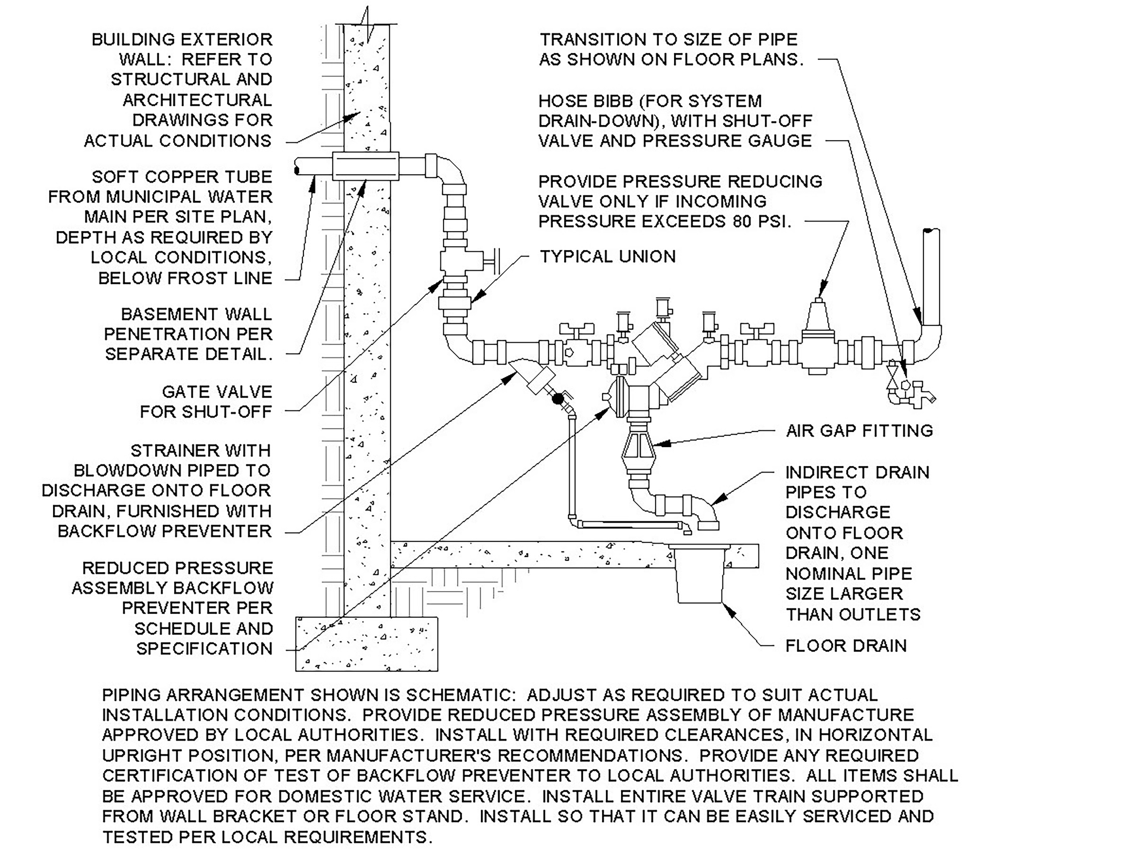
It is normally the responsibility of the civil engineer to coordinate the meter and backflow device with the public works department or local water purveyor. The role of the plumbing engineer is to indicate to the civil engineer the size of the meter and backflow device required for the building (see Figure 1).
Design Challenges with High-Rise Water Systems
Providing domestic potable water for a high-rise building can be challenging. Having adequate water pressure at the top of the building competes with not exceeding
80 pounds/square inch (psi) at each plumbing fixture.
The water pressure available at the water main is typically not enough to supply adequate water pressure to the uppermost floor or the roof. Therefore, the incoming water pressure needs to be increased at the incoming water service inside the building to meet operating pressure requirements.
Overcoming this challenge is achieved by a combination of installing a domestic water booster pump at the point of entry and creating pressure zones via pressure-reducing stations.
Normally, the booster pump discharge pressure will be greater than the pressure allowed at a single fixture in the building. Therefore, pressure-reducing valves (PRVs) must be installed to limit the pressure to 80 psi. This is the highest supply pressure allowed at any given plumbing fixture or piece of equipment.
Providing a PRV at every fixture or floor within the building is cost-prohibitive and wasteful as each PRV needs to be accessible for service. In addition, each valve must have a Y-strainer with a blowdown valve and a drain to maintain and service the valve.
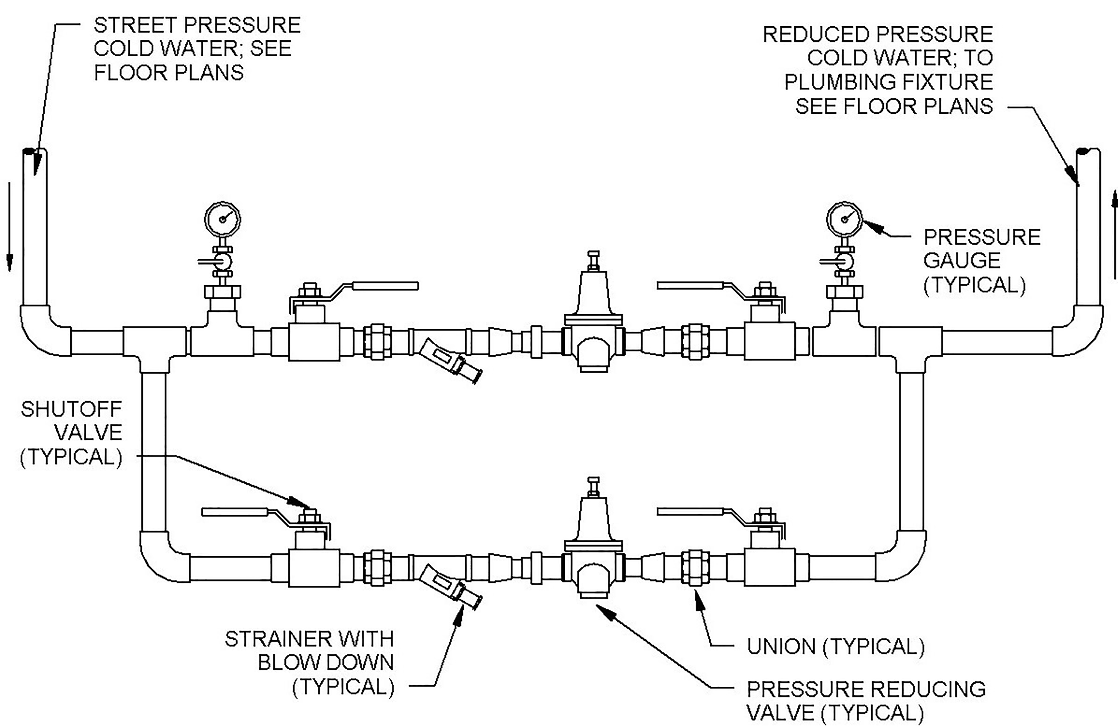
Creating a pressure zone with a PRV station that supplies pressure for a stack of floors with water pressure below 80 psi is recommended. Figures 2a and 2b are a typical PRV station zone assembly used to reduce the pressure in a high-rise building.
 |
 |
Water Piping Material and Valve Considerations
Water piping material and valve types in high-rises must be carefully selected. Care must be taken when designing the high-pressure side of the water system downstream of the booster pump. If not, over-pressurizing the piping system could cause catastrophic damage to the building, tenants and the building’s water system.
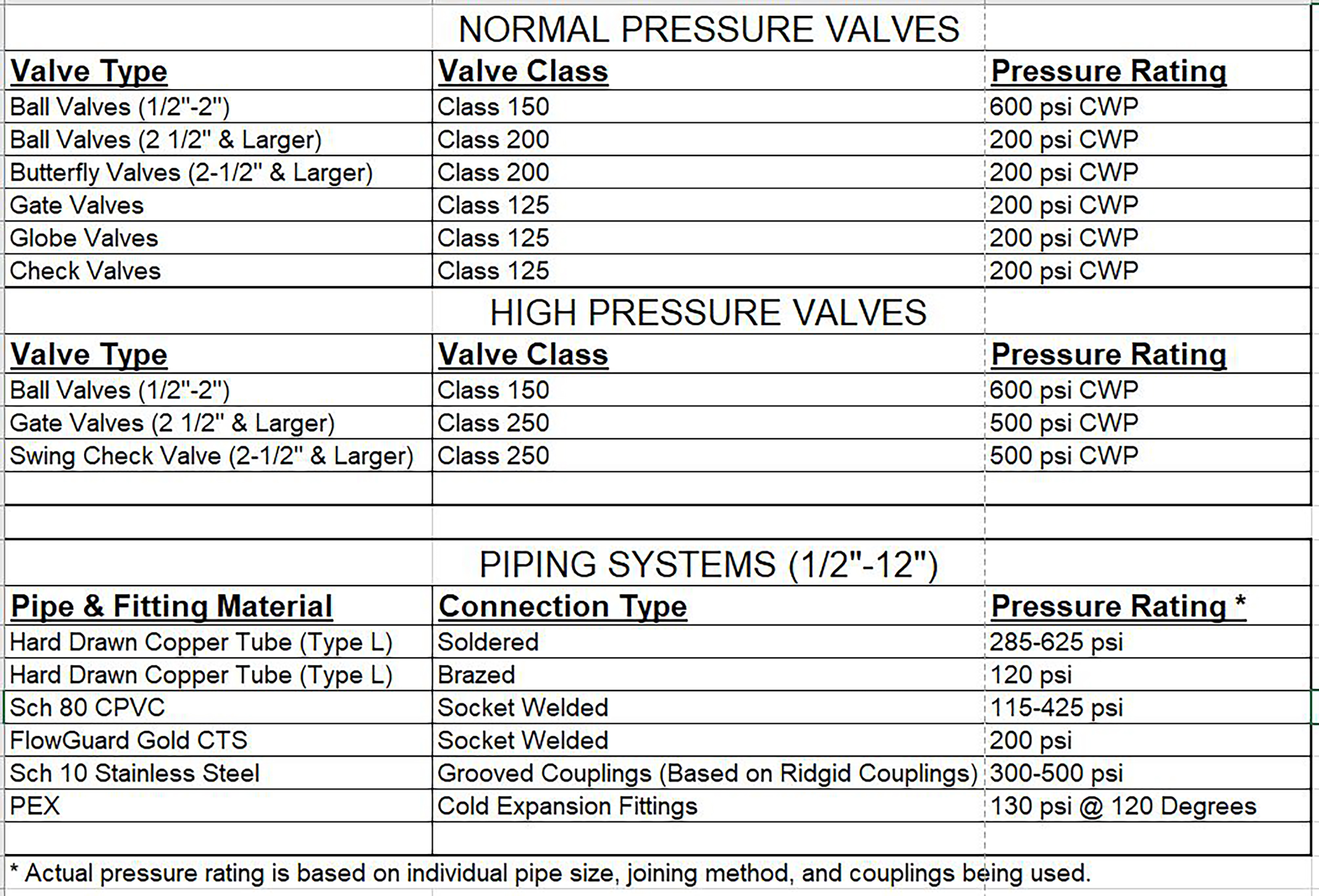
It is not uncommon for the discharge pressure of the booster pump to exceed the pressure rating of pipe joints and valves. Soldered 95-5 hard drawn copper and fittings and Schedule 40 stainless steel with flanged fittings should be used.
Under normal operating pressure conditions, less than
80 psi, Class 125 gate valves 2 inches and smaller or
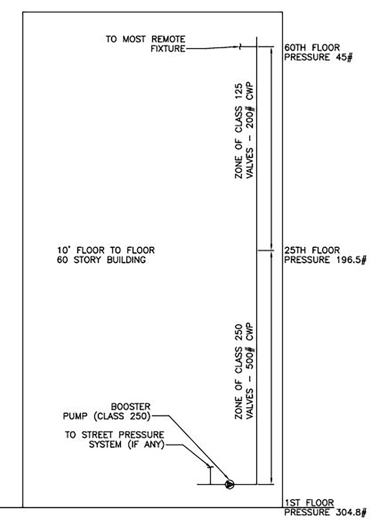
200 CWP ball valves are used for 2 1/2 inch and larger water service. In high-rise buildings, it is common for the lower zone to use Class 250 valves because of the higher-pressure ratings. Figures 3a and 3b show the maximum working pressure for valves and piping where you would typically see Class 125 and 250-rated valves in a high-rise building.
 |
 |
Pressure Reducing Valve and Pressure Zoning
PRVs are used to create pressure zones in high-rise buildings and limit the pressure within those zones to less than 80 psi. When designing the water pressure zones, it is necessary for designers/engineers to take a cross-section of the building to start planning out where the pressure zones will serve.
Depending on how tall the building is, it is highly recommended to have pressure zones supplying between four to eight floors per zone. The reason behind this is to make sure pressures above 80 psi are not exceeded in a pressure zone.
When designing a zone, we want to look closely at the floor-to-floor heights. Most floors in a high-rise are 10 feet from floor-to-floor, except for the ground floor level and penthouse. With 10 feet as the typical floor-to-floor height, we can easily calculate we will lose or gain roughly 4.33 psi per floor. The outlet setting of the PRV will need to be set between 75 and 40 psi.
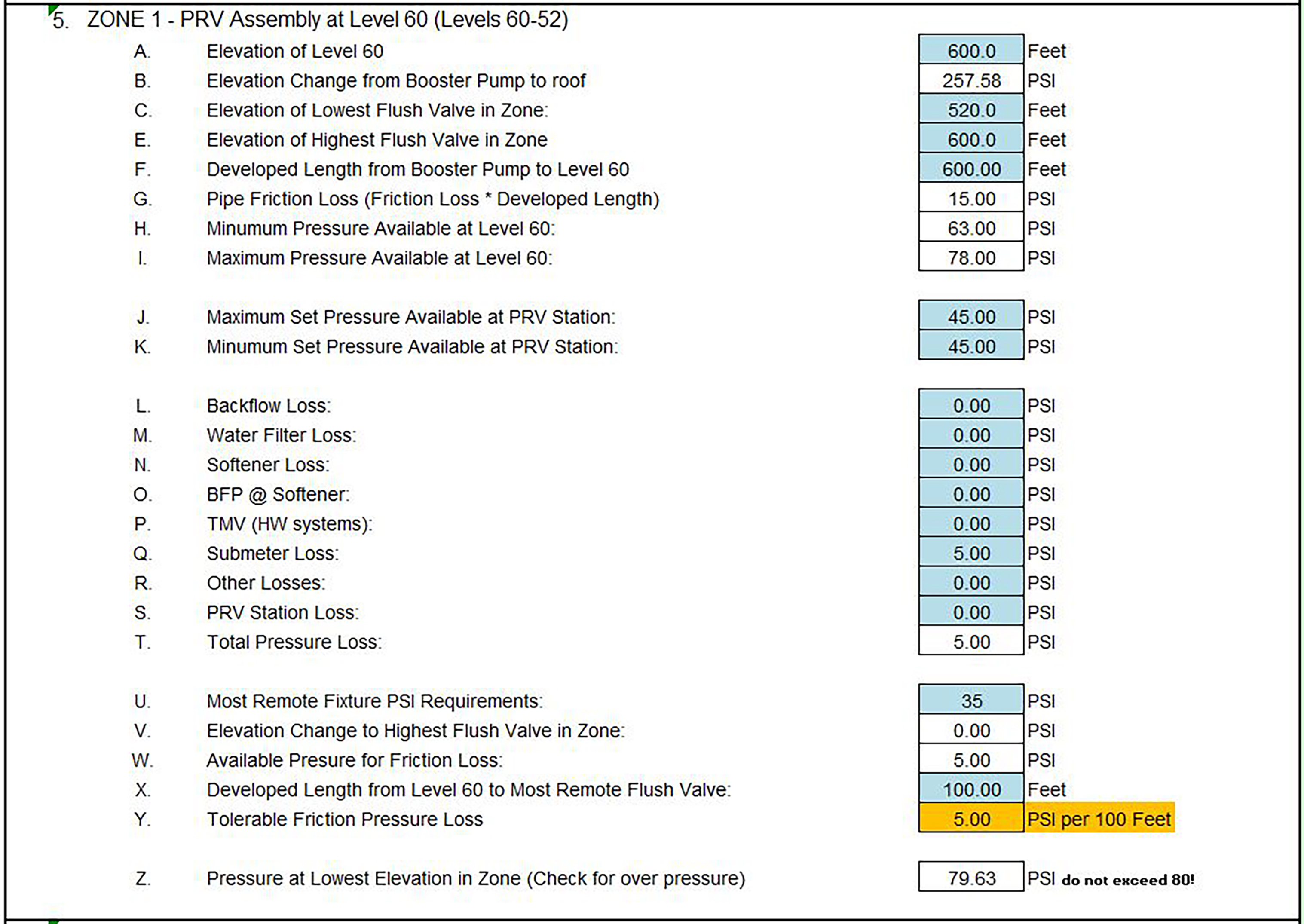
In Figure 4, which shows an example of a 60-story high-rise water riser, Zone No. 1 is the uppermost level in the building. The PRV station setting will be set at 45 psi.

Since the upper-system zone is a down-fed system, we must calculate that the static gain at the lower level of the zone will not exceed 80 psi. Eight floors at 10 feet floor-to-floor = 34.64 psi gain. 45 psi + 34.64 psi = 79.64 psi.
Pressure Zones (Up-Feed Vs. Down-Feed)
Pressure zones in a high-rise can be up-feed, down-feed, or a combination of up- and down-feed. It all depends on what floor the PRV station will be installed on for a particular pressure zone.
Most contractors prefer to install the pressure zone on the lower levels and up-feed the domestic water pipe. This is fine from an installation standpoint.
However, when performing hydraulic calculations, the uniform friction loss for the zone must be calculated by taking the total length from the PRV station to the most remote fixture.
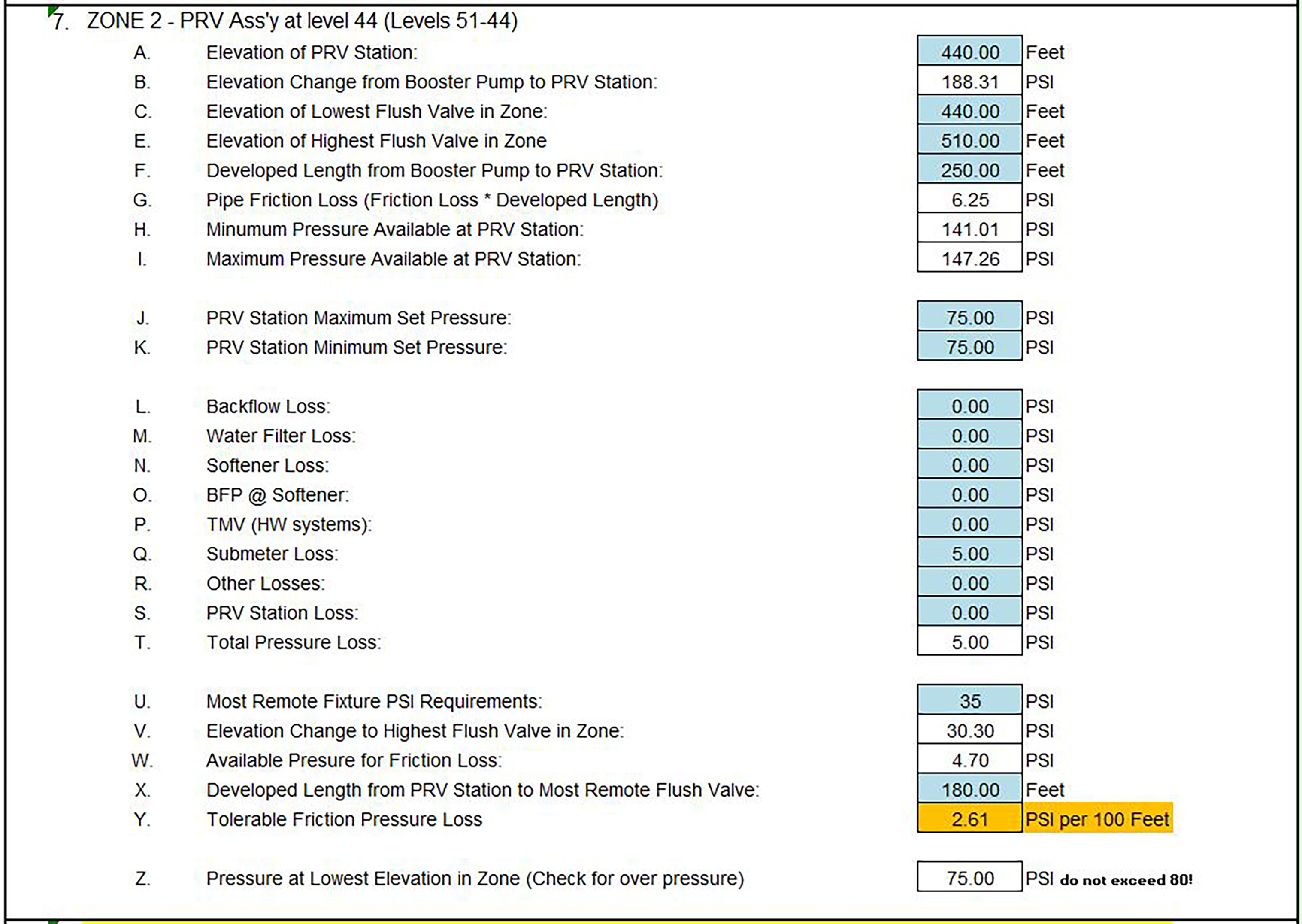
In an up-feed system, the total developed length (TDL) is taken from the most remote fixture furthest away from the PRV station, which in our case is eight floors (80 feet) up to the most remote water closet or governing fixture.
In a down-feed system, the TDL is taken from the PRV station to the most remote fixture on the same floor, thereby reducing the TDL by 80 feet and increasing the psi/100 feet uniform pressure loss. The more pressure loss available within the pressure zone due to reducing the TDL, the smaller the piping will be in the zone.
The difference between sizing a system on 2.6 psi/100 feet and 5 psi/100 feet can save the owner/developer costs related to pipe sizing. The Down-feed System Calculation and Up-feed System Calculation graphics, identified in Figure 5 and Figure 6, respectively, show examples of hydraulic zone calculations.
 |
 |
Designing domestic water systems for a high-rise building has its challenges, but there are several best practices that help ensure success:
Remember the fundamentals of hydraulics, physics of gravity, and make sure to keep the pressure range in a single zone between the minimum pressure required for the plumbing fixture to operate and the code maximum of
80 psi.
Keep a close eye on the maximum pump discharge pressure and the pressure rating of pipe, fittings and valves.
Treat each pressure zone as an independent system from the high-pressure water main.
Coordinate size and location of PRV closets with the architect and ensure there is a drain for blow and drain down of the station.
Karl Caouette, CPD, is a plumbing technical director at Henderson Engineers, a national building systems design firm.


