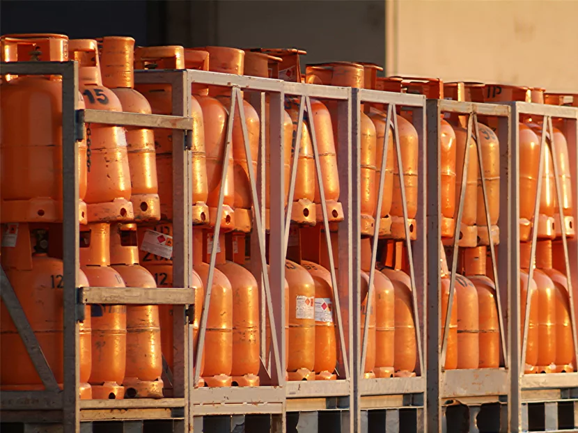
Having been in this business for 32 years, it does come as a surprise when a project calls for a system that I have never designed before. When this happens, it is always interesting doing the research required to embrace this new territory of information. Such was the case on one of my projects where the gas-fired emergency generator required compressed natural gas (CNG) as a backup fuel supply.
In designing such a system, there are two key factors: the load of the generator and the duration of the standby fuel supply. The client dictated the duration as 90 minutes. That was the easy part; the load of the generator was a little trickier.
For whatever reason, the generator load was given in metric units of g/kWh (grams per kilowatt hour). I had never heard of these units before. I researched a conversion, and all I came up with was Btu/pound. I had no idea how to get from there to CFH — the units I needed to calculate the volume of gas required. I was able to source another cut sheet for the generator that listed the demand in both m3/hour and CFH. Interestingly, g/kWh are the same as m3/hour, but I have no idea why. The bottom line was the generator had a demand of 10,135 CFH. For a 90-minute supply, it’s 1½ times the hourly load, so we had to store 15,203 cubic feet of gas.
If you remember Boyle’s Law, the volume of a gas is directly proportional to its pressure (at constant temperature): P1xV1 = P2xV2
Pressures must be used in absolute terms. Since the delivery pressure to the generator is 2 psi, P1 is 14.7 psi plus 2 psi for 16.7 psi (absolute pressure) and V1 is 15, 203 cubic feet.
CNG systems can be run at 2,000 psi, 3,000 psi or up to 5,000 psi. The higher the pressure, the smaller the storage tank(s). At 2,000 psi (2,015 absolute) the tank volume is 942 gallons, or 1,000 gallons nominally:
V2 = 16.7x15,203 / 2,015
V2 = 126 ft3 x 7.48 gal/ft3
V2 = 942 gal.
At 3,000 psi, the volume reduces to 650 gallons, and at 5,000 psi, it reduces further to 400 gallons.
Filling the tank requires a high-pressure compressor. There are several manufacturers; in my search I stumbled across — Sauer, Bauer and Caterpillar, to name a few. The compressor and ancillary components can be purchased in a weatherproof enclosure, which of course is good for an outdoor installation.
As it turned out, I did not need a compressor. CNG trucks can fill the CNG tanks, and since the system is only used in an emergency, it doesn’t make sense to have a CNG compressor sitting around doing nothing; so, all that was required were the CNG tanks themselves.
Since they operate at such high pressure, CNG tanks are usually spherical (a sphere is the best shape to contain a high pressure). The vendor we selected had tanks in 250-gallon increments, so a 5,000-psi system required two tanks to accommodate the 400 gallons of storage.
Another thing to take into consideration is the working pressure of the piping. Schedule 80 steel, depending which reference you use, has a working pressure of 4,100 psi for ½ inch pipe, so this would not be adequate for a 5,000-psi system. For the high-pressure side (upstream of the first regulating station), a high pressure stainless steel piping system, such as Swagelok, is required.
Also, critical to these systems are the pressure regulators. A primary station with two or three parallel valves will reduce the pressure from tank pressure (5,000 or 3,500 psi) to around 1,500 psi. After each PRV, it is important to have pressure relief valves and pressure gauges. The second pressure regulator reduces the pressure to around 150 psi, and the third reduces it to low pressure as required for the generator.
It is important to provide two gas regulators on the utility service for the generator: one that reduces the gas to 5 psi and a second in series that reduces it to 2 psi. The 2-psi gas from the CNG system should connect to the piping in between the two regulators via a check valve. As such, under normal conditions the 5-psi gas will keep the CNG check valve closed. If pressure is lost from the utility main, the 2-psi CNG will automatically take over as the source of supply. No valves need to be closed, and no electric actuation is required to switch to the CNG backup.
On a final note, protection of the CNG tanks is important, although I don’t know that it is necessarily a code requirement. In this day and age, one has to plan for the worst possible scenario, such as a sniper who can’t resist the CNG tank as a target. I don’t know that a bullet of any kind would be able to puncture the thick-walled steel tanks, but I wouldn’t want to test it. If the tanks were outdoors, I would recommend a block wall be built to enclose and protect the tanks. This should be discussed with your architect since there may be other building code requirements associated with this enclosure.
I hope everyone has a very happy holiday and 2018!


