
An important and often overlooked aspect of fire protection is the flushing of the underground piping prior to connection with the aboveground piping. The importance of this flushing is magnified when both the fire hydrants and the building sprinkler systems are supplied by a pressurized loop with multiple lead-ins, as is the increasing trend for warehouses.
These layouts are becoming more common because they allow a reduction in bulk main piping by using already required underground piping used for hydrants, reduce structural loads by reducing large diameter piping hung from the structure (for interior loops), and could eliminate the need for a pumper to pressurize the fire sprinkler systems through the fire department connection (FDC).
The reason proper flushing protocol is important is that it prevents debris from impairing or disabling water-based fire protection systems. During the installation of underground piping, open-ended piping is installed in trenches that invariably collect dirt, rocks and miscellaneous equipment from the installing contractors — ranging from safety gear to construction material.
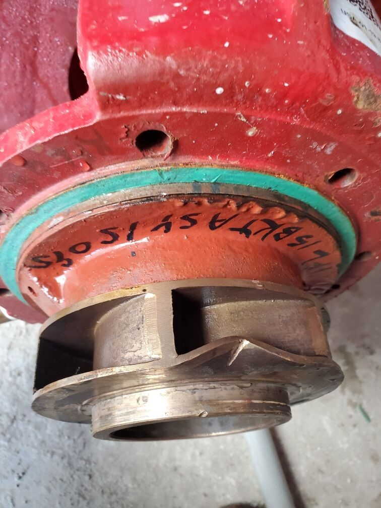
Failure to remove this debris from piping upstream of the fire pump can damage or destroy the pump impeller (see Figure 1), which, in turn, may cause delays to the project schedule. Failure to remove this debris downstream of the fire pump can result in a reduced flow rate due to obstructed valves, piping and sprinkler discharge orifices.
Flushing is often overlooked because the typical project uses multiple installing contractors for installation. The typical construction project has an underground utility contractor that installs the underground piping and valves up to a flange located 1-foot above the building’s finished floor, after which the sprinkler contractor’s scope of work starts.
The underground system installation may be completed months before the sprinkler contractor’s scope of work starts. Therefore, a strong general contractor (backed up by a strong fire protection engineer of record) is needed to maintain coordination between subcontractors and ensure the underground system installation and acceptance testing is well-documented before the connection of the overhead sprinkler systems’ piping.
Beware of any system that does not have proper documentation of flushing, as we have personally witnessed enough dirt and rocks to fill a small pickup truck bed coming out of systems that “have already been flushed.”
Upon completion of the underground fire service line hydrostatic test, the underground piping should be flushed and witnessed by the local fire officials. In most jurisdictions, flushing must be completed before lead-in connections and installation of the sprinkler risers to the overhead piping.
Flushing Plan Coordination
To adequately flush the system, stakeholders including but not limited to the general contractor, underground utility contractor, sprinkler contractor, fire department/authority having jurisdiction, water authority, paving contractor and landscaping contractor should be involved. The underground utility contractor is responsible for conducting the flushing and submitting the required documentation in accordance with NFPA 24, Standard for Installation of Private Fire Service Mains and Their Appurtenances.
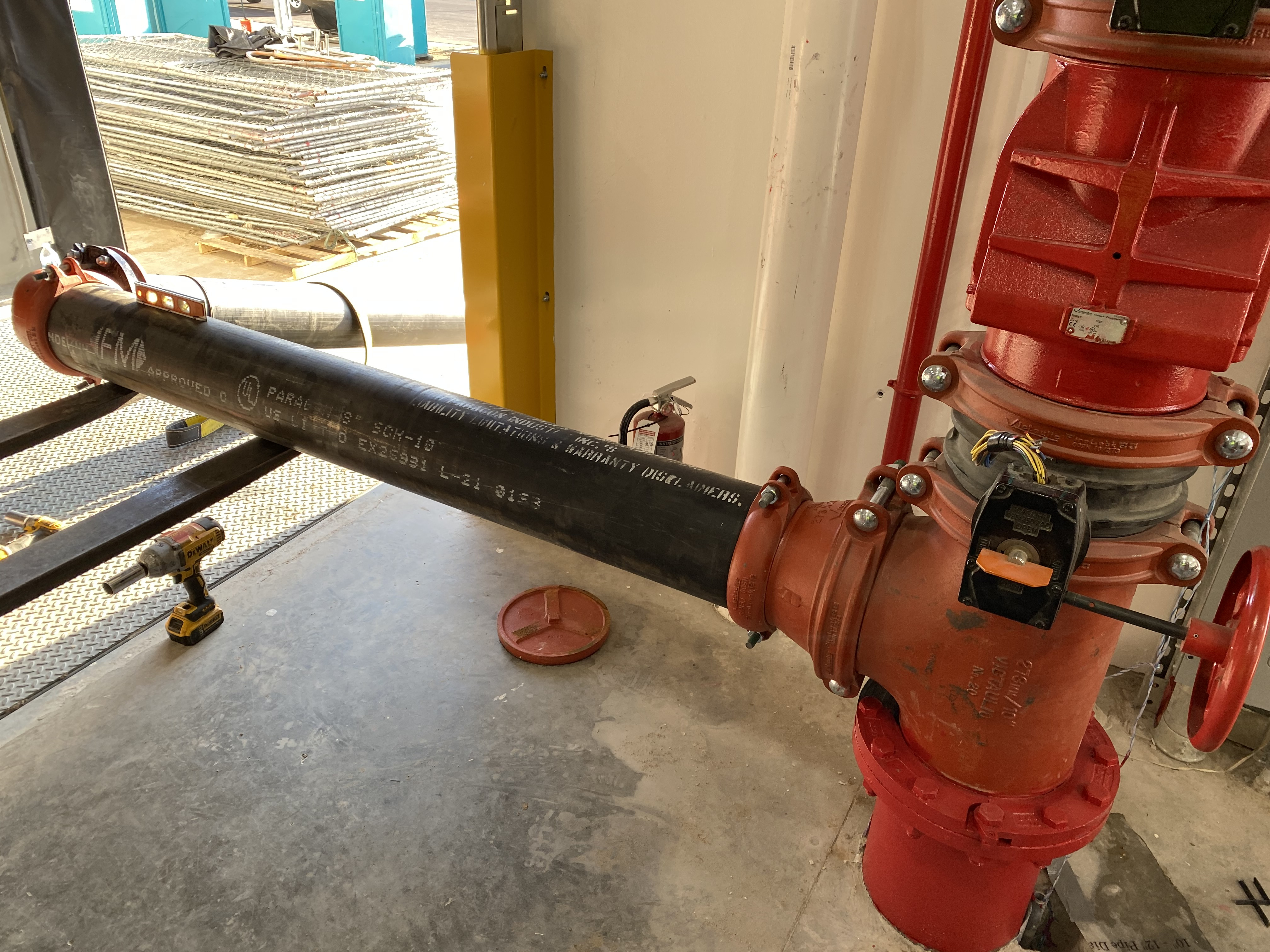
Where the municipal water supply is not sufficient to achieve necessary flushing velocities, the sprinkler contractor will be needed to operate the fire pump or a temporary trailer-mounted pump if the planned fire pump is yet to be installed and tested. Additionally, the sprinkler contractor generally needs to be involved with attaching a flushing rig (see Figure 2) to the interior lead-in to discharge flushing water to the exterior of the building.
Fire officials usually want to witness the flushing of underground mains to ensure debris does not damage their fire engine’s pumps and to ensure debris does not obstruct the fire sprinkler system. Depending on the length and sizes of piping, flushing underground mains (especially when looped) can require hundreds of thousands of gallons of water; therefore, coordination to minimize the impact on the municipal water system is advisable.
The public water district purveyor should be consulted and advised that the underground flushing will likely flow a large volume of water and the potential for large or sustained water pressure drops in the system. Due to the possibility of both water damage and impairment to the project schedule, the paving and landscaping contractors should also be included in the flushing coordination.
Flushing Procedure
The requirements and procedures to properly flush underground water supplies are found in NFPA 24. This standard requires all piping from the water supply point of connection to the incoming fire pump suction lead-in to be flushed at a minimum velocity of 15 feet/second before connection with the fire pump. Piping downstream of the fire pump is flushed at a minimum velocity of 10 feet/second before connection with aboveground sprinkler systems.
Before flushing is scheduled, an agreed-upon plan should be reviewed by the underground utility installation contractor and flushing team. The water supply information used for system calculations will be needed to determine the maximum quantity of water that can be supplied by the municipal system for flushing. Most jurisdictions forbid reducing pressures upstream of the backflow preventer below 20 psi, and some water systems have additional, more stringent requirements.
On the same day but before flushing, a flow test should be conducted to confirm the available flow/pressure relationship at the time of flushing. If the water supply is weaker than the flushing plan expected, the plan will need to be modified.
To flush a piping loop, a pathway that starts at the pump and covers more than 50 percent of the loop needs to be chosen. Control valves should isolate the loop to only flow in a single direction (let’s use clockwise for this example). The water is forced around the loop and through a lead-in and discharged out of a riser manifold by way of a flushing rig to discharge to grade.
After the piping is flushed in the clockwise direction, the loop should be flushed in the opposite (counterclockwise) direction. It is important to flush the loop counterclockwise to a point past the previous lead-in used to discharge the water such that there is an overlap between the flushing of the two “partial” loops. Once the entire loop is flushed, the individual building, hydrant and FDC lead-ins can be flushed.
Piping that was previously flushed as part of the loop flushing does not need to be included.
Flushing duration is equal to the total length of pipe flushed divided by the actual flow rate. It is recommended that a safety factor of two should be applied to the minimum flushing duration to account for larger objects that may be rolling along the bottom of the pipe rather than traveling within the water stream. If the flushing duration is met and the water discharging from the flushing rig continues to have evidence of debris at the discharge, the flush should continue until the water is clear.
If the project has a remote/freestanding FDC that discharges directly into the loop, it is important to confirm that the check valve is accessible and can be rotated in the opposite direction so that the FDC lead-in can be flushed out of the FDC. If this check valve is not accessible, then the FDC lead-in must be flushed through the FDC into the loop prior to flushing the loop. The latter can be complicated by the various FDC outlet connection types (NHS vs. Storz).
Testing Equipment
In addition to the flushing procedure, additional equipment is required for a successful flushing operation. A flow test kit including gauges calibrated within the last year is a must for determining the water supply upstream of the fire pump. To control the water flow path, ensure the proper wrenches are available to open and close underground sectional valves.
The piping used for flushing (flushing rig) should be extended to the outside of the building at a safe location and to areas that will not cause water to accumulate, build up and enter a structure or a hazardous area or damage the site.
Testing rigs attached to the riser manifolds usually consist of piping, a control valve and fittings needed to pipe to the exterior through adjacent man doors or dock doors. These testing rigs should never be secured in place by personnel.
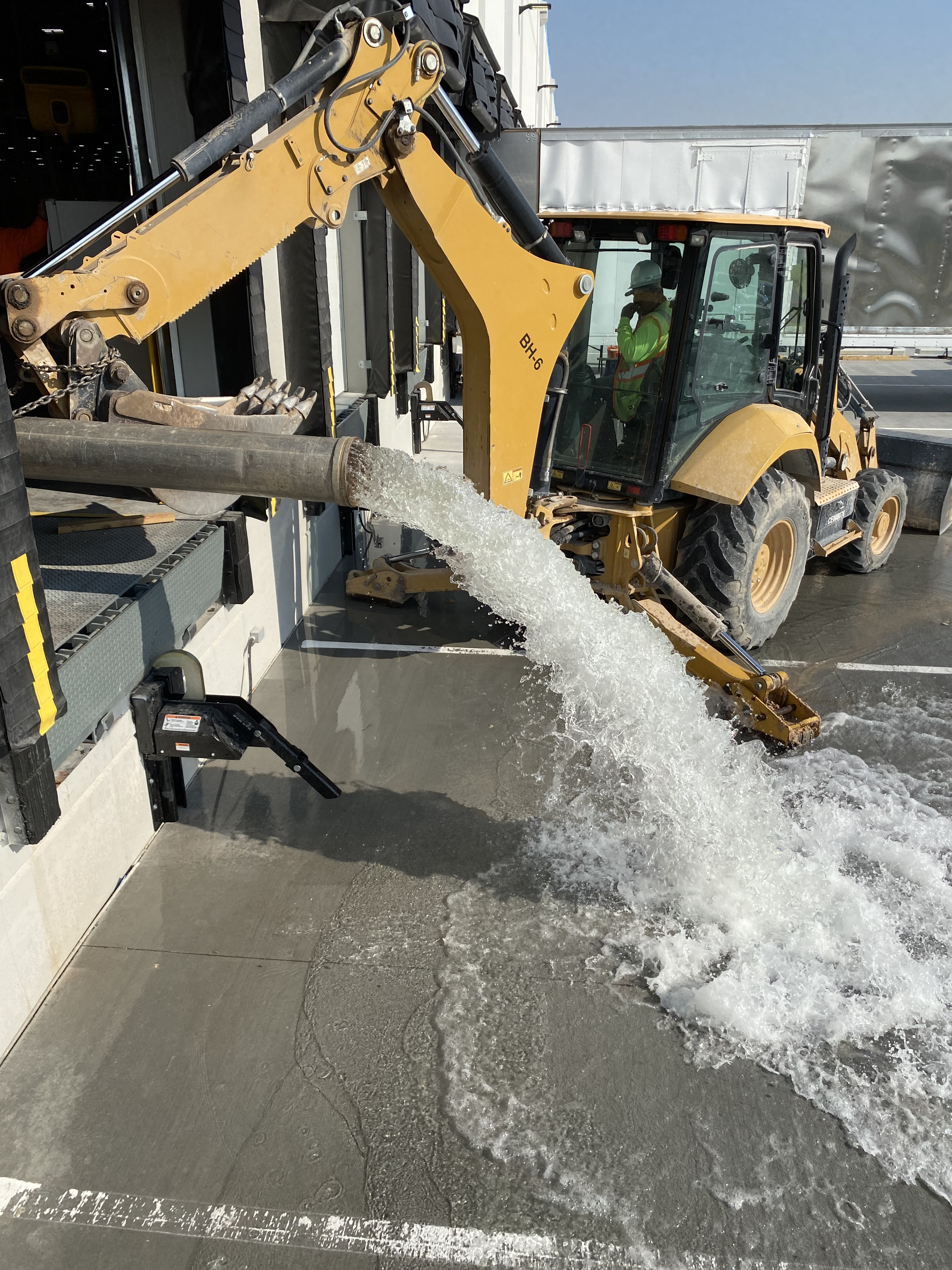
Due to the forces placed on the test rig by the flowing water, it is recommended that it be securely attached to heavy equipment such as a forklift, front loader or trailer (see Figure 3). Including site safety personnel is recommended and can enhance the safety of the flushing
operation.
Testing rigs that discharge into the bull end of a tee fitting add stability to the rig as water discharges through both outlets (sides) of the tee and the resultant reaction forces are offset. Often a burlap bag is attached to the discharge of the test rig as a strainer to collect recovered objects. Our experience indicates that test rigs that discharge to large, paved areas do not need a strainer to collect objects that are flushed from the underground piping.
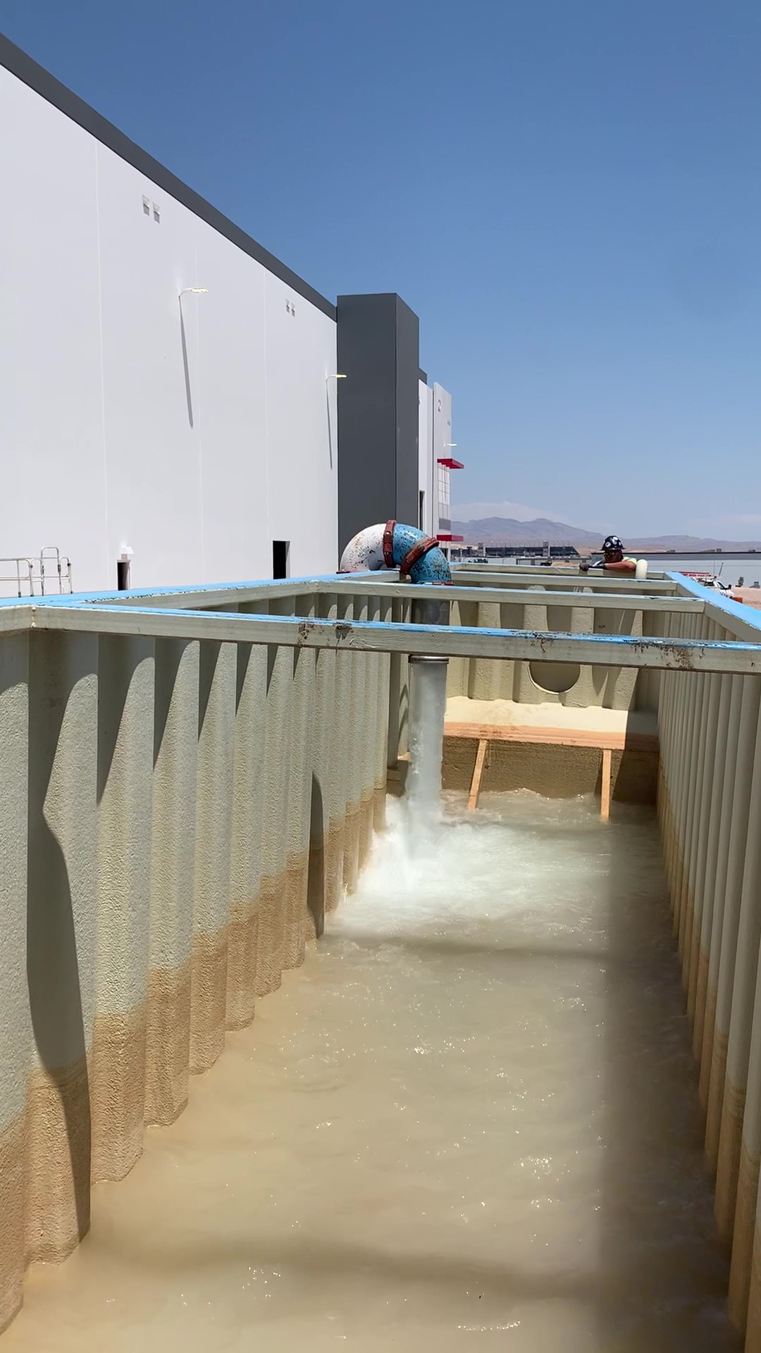
Where the discharge of the flushing water will damage landscaping (or grading done for future landscaping), the test rig can be configured to discharge into a large vessel and subsequently pumped or otherwise drained to a safe location (see Figure 4).
The testing plan should give clear instructions to the flushing contractors regarding the sequence of flushing, valves required to be opened or closed, testing equipment and duration of flush. In general, it is recommended to first have a coordination meeting with the flushing team in advance so that all parties involved are prepared and have a clear understanding of the flushing procedure and equipment needed to complete the testing.
The underground fire service line from the water supply to the sprinkler system risers should be completely flushed in accordance with NFPA 24 and local authority having jurisdiction requirements before any connection is made to the aboveground fire protection system piping.
Warehouses and other buildings with pressurized underground looped supply piping require a well-thought-out and well-executed plan to ensure the systems are ready to connect to the aboveground sprinkler systems and fire pump(s). Proper coordination between all stakeholders throughout the project fulfills fire protection engineers’ obligations to their clients and the public to provide fire service connections free from potential obstructions. l
Thomas W. Gardner is a senior vice president/senior project manager with the Harrington Group. He is a licensed professional engineer (fire protection) in 16 states and has more than 41 years of experience. Gardner is a fellow in the Society of Fire Protection Engineers (SFPE), past chair of the National Fire Protection Association (NFPA) Health Care Section, and past chair of the SFPE Engineering Education Committee.
Eric Okurowski is a fire protection engineer with the Harrington Group. He is a licensed professional engineer (fire protection) in five states and has more than 11 years of experience. Okurowski is a member of SFPE and NFPA.
Jonathan Samuel is a fire protection consultant with Harrington Group and has been working in the fire protection engineering industry since 2006. His areas of expertise include fire alarm system design, fire suppression system design and system commissioning.


