This is a continuation of a summary of the significant code changes to the 2021 Uniform Plumbing Code (UPC) which is developed and promoted by the International Association of Plumbing and Mechanical Officials. These code changes will appear in the 2021 edition of the International Plumbing Code. Because it is possible for modifications to be made during the final hearing process and because there were multiple changes made to some code sections, the final edited version may be slightly different than what was in the actual code change proposal. Refer to the 2021 International Plumbing Code for the final version of any code changes.
The proposed new code language is underlined. The text proposed to be deleted is stricken through. The proposed changes are followed by the proponent’s published reason statements, and occasionally by my comments when noted.
Code Change: 2021 UPC Code, Chapter 6, Section 608.2, Table 1701.1
Revise the text sections and tables as follows (the remaining text is unchanged):
608.2 Excessive Water Pressure.
608.2 Excessive Water Pressure. Where static water pressure in the water supply piping is exceeding 80 psi (552 kPa), an approved-type pressure regulator preceded by an adequate strainer shall be installed and the static pressure reduced to 80 psi (552 kPa) or less. Pressure regulators for potable water distribution systems shall comply with ASSE 1003. Pressure regulator(s) equal to or exceeding 11⁄2 inches (40 mm) shall not require a strainer. Such regulator(s) shall control the pressure to water outlets in the building unless otherwise approved by the Authority Having Jurisdiction. Each such regulator and strainer shall be accessibly located aboveground or in a vault equipped with a properly sized and sloped bore-sighted drain to daylight, shall be protected from freezing, and shall have the strainer readily accessible for cleaning without removing the regulator or strainer body or disconnecting the supply piping.
Pipe size determinations shall be based on 80 percent of the reduced pressure where using Table 610.4.
An approved expansion tank shall be installed in the cold water distribution piping downstream of each such regulator to prevent excessive pressure from developing due to thermal expansion and to maintain the pressure setting of the regulator. Expansion tanks used in potable water systems intended to supply drinking water shall comply with NSF 61. The expansion tank shall be properly sized and installed in accordance with the manufacturer’s installation instructions and listing. Systems designed by registered design professionals shall be permitted to use approved pressure relief valves in lieu of expansion tanks provided such relief valves have a maximum pressure relief setting of 100 psi (689 kPa) or less.
Revise the text sections and tables as follows, (the remaining text is unchanged):

Proponents’ reason statement: The appropriate standard for this application is ASSE 1003. It is currently unclear what the criteria for acceptance are for pressure-reducing valves (PRVs) other than being “an approved type.” A device compliant with ASSE 1003 is required to control the downstream pressure to the setpoint, and only vary by 1 psi for every change in 10 psi of the inlet pressure.
As an alternative to ASSE 1003, the UPC already states that other viable options are available by way of Section 301.2, or as stated in this section: “or method acceptable to the AHJ.” ASSE 1003-compliant devices are self-contained, direct-acting, single-diaphragm types. Devices are permitted to have an integral strainer, separate strainer connected to the valve inlet, or be without a strainer. Devices are permitted to be with or without an integral bypass relief valve.
Example tests performed within ASSE 1003 are a hydrostatic test, a maximum temperature test, the ability to reduce pressure from 250 psi to 25 psi, the ability to control the reduced pressure to 10 percent of line inlet variations, a flow capacity test, an adjustment pressure range test, and a bypass relief valve test. The original proposal used the term "domestic water distribution systems" and is not defined. There was a modification proposed to use the word "potable" to clarify the type of water system being applied
My comments: Standard ASSE 1003, Performance Requirements for Water Pressure Reducing Valves for Potable Water Distribution Systems, is only for PRVs of the direct-acting type, where an adjustment can be made to change the tension on a spring. This applies a force to a valve stem that causes a fixed, yet adjustable pressure drop across a valve.
For example: If the water pressure supplied to a building is 120 pounds/square inch (psi), the PRV creates a pressure drop such that the spring exerts enough force against the valve seat to cause the valve to have a 40-psi pressure drop so that the downstream pressure is 80 psi when the upstream pressure is 120 psi. PRVs should always have a control valve and a pressure gauge on the inlet and outlet to allow for adjustment and maintenance.
If the user decides they want 70-psi downstream pressure, simply adjust the nut or screw on top of the pressure-reducing valve while water is flowing and read the downstream pressure gauge. As the adjustment is made to increase the tension on the spring to cause a 50-psi loss across the valve, thereby a 70-psi outlet pressure will show on the downstream pressure gauge
For larger PRVs, they are typically of the pilot-operated type, which allows the upstream pressure to work with a diaphragm to help control the pressure drop across the valve seat. Pilot-operated PRVs typically conform to standard AWWA C530. These are generally used in the larger of higher-pressure-engineered pressure-reducing applications with water, gas and steam.
The AWWA C530 standard should have also been listed in this code change. There has been an effort by the industry to add these ASSE standards to the codes. The ASSE 1003 standard covers the direct-acting type of PRV.
In Figure 1, the direct-acting valve outlet (downstream) pressure can be adjusted by turning the screw/bolt on top of the valve, which changes the tension on the spring. Adjusting the spring tension helps the valve open and close, which can increase or decrease the downstream pressure.
It is always good design to provide a strainer upstream of the PRV and a shut-off valve, as well as a pressure gauge on each side of a direct-acting PRV. Devices covered by the ASSE 1003 standard are self-contained, direct-acting, single-diaphragm-type PRVs. They shall be permitted to have an integral strainer, a separate strainer connected to the valve inlet or be without strainer.
Devices shall be permitted to be with or without an integral bypass relief valve, which allows downstream pressure to relieve back to the inlet side of the valve, but the relief valve will only operate when the downstream pressure exceeds the upstream pressure. Therefore, if there are any piping, fixtures or equipment that must be protected from higher upstream pressures, a separate pressure-relief valve must be installed on the downstream piping to relieve the excess pressure in order to protect downstream piping, fixtures and equipment.
The relief line should be sized and routed to an adequately sized drain or place of discharge so as not to cause flooding, physical harm or property damage. It should be installed in accordance with indirect waste or relief valve requirements in the code. Size ranges for ASSE 1003 valves are 1/2, 3/4, 1, 1 1/4, 1 1/2, 2, 2 1/2, 3 and 4 inches (DN 15-100).
ASSE 1003 devices must be capable of withstanding a minimum working pressure of 250.0 psi (1723.8 kPa). In piping systems where the pressures are higher than 250 psi, an engineer should specify the proper pressure rating for the piping, valves and fittings based upon the pressures in the system.
The temperature range for ASSE 1003 devices are for temperatures of 33 F (0.6 C) to 140 F (60 C) minimum.
A pilot-operated PRV (Figure 2) uses the water pressure to help add force to the diaphragm to control downstream pressure. Because of the many small waterways and because debris caught in the valve seat can cause the downstream pressure to equalize, a strainer is recommended ahead of any control valve.
Often PRVs are part of a pressure-regulating station, where two or more pressure regulating valves are installed in parallel and set to slightly different pressures to allow for better control. Isolation valves and pressure gauges on both sides of each valve are important for adjustment and maintenance.
The scope of Standard AWWA C530, Pilot Operated Control Valves, establishes the minimum requirements for pilot-operated control valves of globe, angle and wye body styles with various end connections in sizes from 1 1/2 inches through 60 inches in diameter (37.5 mm through 1,500 mm), with water having a pH range from 6 to 9 and a temperature range from 40 F to 125 F (4.4 C to 52 C).
The standard covers piston- and diaphragm-type valves suitable for a maximum steady-state fluid working pressure of 300 psig (2,070 kPa), a maximum steady-state differential pressure of 300 psig (2,070 kPa) and a maximum line velocity of 15 feet/second (4.6 meters/second).
The AWWA C530 standard covers various pilot-operating methods in pressure classes described as pressure classifications from pressure classes of: 125 psi, 150 psi, 250 psi and 300 psi; ASME flanges, National Pipe Thread (NPT) and grooved joint ends in sizes 1 1/2 inches to 60 inches (37.5 mm to 1,500 mm). The AWWA C530 standard should be considered for addition to the plumbing code as these types of valves are often used for pressure regulation in pipe sizes 1 1/2 inches and larger.
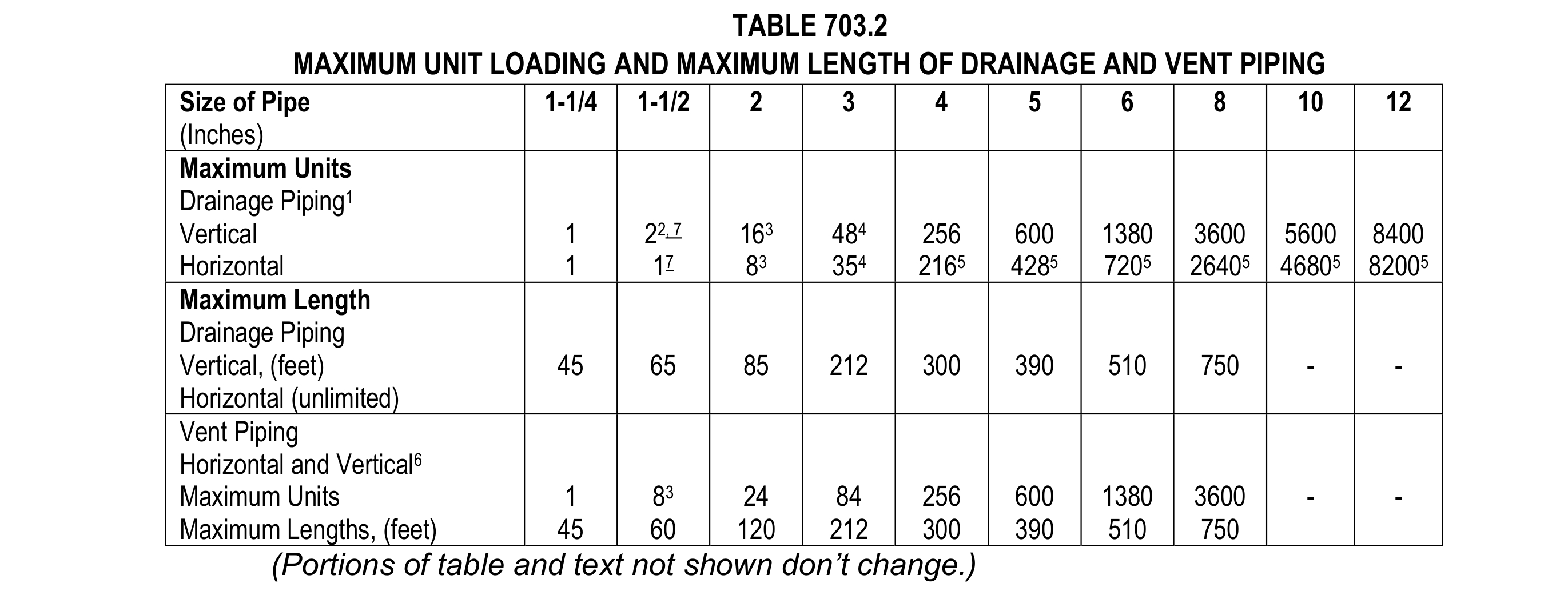
Code Change: 2021 UPC Code, Chapter 7, Table 703.2
Revise the text sections and tables as follows (the remaining text is unchanged):

Notes: (1-6 don’t change)
7. Up to 8 public lavatories are permitted to be installed on a 1-1/2 inch (40 mm) vertical branch or horizontal sanitary branch sloped at ¼ inch per foot (20.8 mm/m).
Proponents’ reason statement: Two-inch drains are inappropriately required for horizontal sanitary branches carrying the discharge of two or more lavatories. These conditions have a flow area of 7 percent and a flow velocity of 0.67 feet/second, which is well under the 2 feet/second cleansing velocity that serves as the basis for UPC pipe sizes and other model plumbing codes.
Given that public lavatories are limited to a maximum of 0.5 gallons/minute flow rates and generally do not have basin-filling functionality, the flow rate of the faucet may be the only flow considered. A flow of 4.78 gpm will occupy 50 percent of the pipe area in a 1 1/2-inch horizontal drain and will flow at a velocity of 1.74 feet/second when sloped at 2 percent.
Nine simultaneously discharging lavatories will create a flow of 4.5 gpm and 48 percent of the flow area in a 1 1/2-inch horizontal drain; therefore, giving eight lavatories with fixture units a sizeable safety factor. The impact of this exception will be substantially easier installation and coordination with insulated water supply piping when fitting in a 4-inch stud wall. A Manning Equation Table document was provided for the Technical Committee to review.
Code Change: 2021 UPC Code, Chapter 8, Section 814.
Revise the text as follows:
UPC 2021 Section 814.0 Condensate Waste and Control.
814.5 Point of Discharge. Air-conditioning condensate waste pipes shall connect indirectly, except where permitted in Section 814.6, to the drainage system through an air gap or air break to trapped and vented receptors, roof drains, dry wells, leach pits, or the tailpiece of plumbing fixtures. A condensate drain shall be trapped in accordance with the appliance manufacturer’s instructions or as approved.
Exception: Where permitted in Section 814.6.
814.6 Condensate Waste From Air-Conditioning Coils. Where the condensate waste from air-conditioning coils discharges by direct connection to a lavatory tailpiece or to an approved accessible inlet on a bathtub overflow, the connection shall be located in the area controlled by the same person controlling the air-conditioned space
Proponent’s reason statement: The proposed text removes any ambiguity by adding the exception to the bottom. Furthermore, roof drains are being added as it is an appropriate location for air-conditioning condensate waste pipes to connect indirectly.
This is a continuing series covering significant code changes from the 2018 to the 2021 edition of the Uniform Plumbing Code. It will continue next month.


