For the experienced plumbing and heating professional, high-efficiency hydronic systems are the “go-to” technology for solar thermal, renewable energy and alternative energy applications in buildings. There are always ample opportunities in any hydronic installation to reduce conventional fuel consumption and upgrade the thermal efficiency. And the familiar principles that govern any ‘radiant heating’ or ‘hot-water boiler’ system also apply to solar/renewable hydronic installations.
In our work with solar hydronic and renewable energy systems over the past 15 years or so, we have been involved in a number of commercial projects that proved to be both innovative and successful. We have combined a variety of different alternative thermal energy sources from one job to the next including…
- Solar heat collectors;
- Air conditioner waste heat recovery from whole buildings;
- Engine-generator waste heat recovery;
- Wood burning boilers (Including wood gasification boiler);
- Hydronic heat pumps (Including reversible heat/cool and DHW); and
- Night sky radiant cooling (Using the solar heat collectors at night for cooling).
The alternative energy sources have been combined with each other, often paired with conventional boilers used as backup for the alternative energy equipment. This is a practical menu of thermal sources that can be mixed and matched depending on the job.
While this may seem a bit daunting, we have found that by using a systematic and consistent design approach, the alternative energy part of the installation becomes very similar (and no more difficult) than any other ‘hot water boiler’ plumbing. When following a proven, repeatable design strategy, these installations become easier and faster to deploy, and with highly dependable results. This design strategy has come to be known as the “New Standard” solar/hydronic combisystem, and I am happy to share it with anyone who can use it. Here are some details and examples of how we have tamed these “multi-source, multi-load” thermal hydronic systems, with examples from two of our most far-flung commercial installations.
Standardized piping configuration
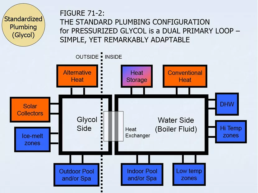
In Figure 71-2, you can see a basic block diagram of the New Standard piping configuration. I have used this pattern (with minor variations) in virtually every thermal hydronic combisystem I have designed over the past decade or so. It has evolved into a “dual primary loop” that contains closed-loop pressurized glycol in the plumbing that extends outdoors, and uses closed-loop pressurized water as the boiler fluid indoors. This configuration can accommodate a wide variety of heat sources and heat loads of various temperatures, and can be easily expanded from the very small to the more complex installations in buildings (or multiple buildings) of various sizes. The block diagram shows a relatively large system with two heat sources and four major heat loads indoors, and two intermittent heat sources and two heat loads outdoors. Solar heat is not the only alternative energy that can be included in a New Standard system. Any combination of multiple heat sources can be grouped together as shown in red in Figure 71-2, including wood-fuel boilers, heat pumps, waste heat recovery or any other heat source, either ‘on-demand’ or ‘intermittent’.
The most important design strategy using this configuration is that any major heat source or heat load can be included or excluded from the design simply by ‘plugging’ or ‘unplugging’ a secondary loop with two pipes (two closely spaced tees). And, any existing secondary loop can be ‘turned on’ or ‘turned off’ at any time under intelligent control simply by operating its circulator pump. Any secondary can either be included or bypassed depending on temperature and priority, including the heat-storage water-tank. This provides an adaptable hydronic plumbing configuration that can be deployed and operated in a modular way at the highest thermal efficiency. The matching control system can also be adaptable and modular to match the predictable patterns of piping and other components used here.
Cold climate example: Beaver Village, Alaska
Beaver is a small First Nations village with approximately 80 residents. It is located in a remote area north of Fairbanks, on the north bank of the Yukon River in a very cold winter climate. Electricity is provided by diesel generators that run 24/7. Potable water is stored and distributed to the village from large central tanks, and of course the water storage and distribution system must be freeze-protected. There are three public buildings that contain services used by the entire village:
- Water Plant/Washiteria building;
- Generator/Workshop building; and
- Clinic/Tribal Office building.
By arranging the heat sources and heat loads around a primary loop in the correct temperature order, this collection of equipment becomes an integrated standard heating system that can be centrally controlled using our standard control strategies. Figure 86-1 shows a block diagram based on the original concept that we gave to the installer. A detailed piping diagram based on this concept was provided as the final plan to retrofit the heat piping that began to take shape in 2014. The system has been operational since February 2015, and the control system has been sending data to us over the internet since then.
Notice that there is a rectangular outline drawn around the equipment on the left of Figure 86-1, indicating that all this equipment is located in the Generator/Workshop building. The equipment outlined in the center of the diagram is located in the Washiteria/Water Plant building. The equipment on the right is to be located in two other buildings as labelled. When hydronic fluid is circulated from one building to another for shared heating, it is known as district heating. In this case, the district is rather small, including (at the most) only four buildings, and they are not very far apart. The buildings are connected together by well-insulated underground heat tubing that is part of the primary loop on the left, and consisting of secondary loops on the right. Because we have not deviated from our typical standard primary/secondary loop configuration, the whole system can be controlled centrally with our usual internet-enabled control system without any custom modifications.
Since the solar and bio-mass heat is slated for future installation, the major heat sources currently in operation are the boilers and the generator waste heat. All reports so far indicate that the generator waste heat recovery has been so effective, that this is doing the lion’s share of heating everything on the primary loop so far, saving many thousands of dollars in boiler heating fuel each year. See Figure 103-1 for photos of the generators and some of the buildings.
Warm climate example: Zemi Beach Resort, Anguilla
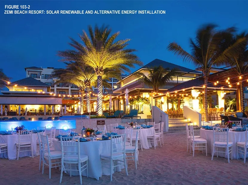
The Caribbean island of Anguilla is only 16 miles long and 3 miles wide, but can boast of some of the most beautiful beaches in the world. On the north side of the island, there are several new resort hotel buildings with easy access to the white sand beaches, palm trees and clear blue water there. During construction, a serious effort was undertaken to make these new buildings as energy-efficient and ‘green’ as possible. That includes renewable and alternative heating for the domestic hot water (DHW) and indoor spa-pools. See Figure 103-2 for a beach-side view of some of these buildings.
The climate here is mostly sunny and warm all year round, and sometimes a little too humid for comfort. So, air conditioning (A/C) is installed throughout these buildings to manage the heat and humidity, but as efficiently as possible. Conventional energy rates are high, for example, the local electricity provided by diesel generators costs 4 to 5 times more than we typically pay in the U.S. Propane is available for backup heat, but is also equally expensive. It makes good sense to offset conventional energy with solar energy, and to recover waste-heat as well. In these new buildings, the A/C system includes the use of hydronic heat exchangers that allow the heat that is normally rejected to the outdoors to be collected and used to make hot water.
As it turns out, this is also an ideal application for a New Standard thermal hydronic combisystem. And just such a system was designed and installed to manage the thermal energy efficiency in the first three (of four) hotel buildings to be completed. Figure 73-1 shows a photo of the solar collectors on the day they were mounted on the roof of the first hotel building, July 4, 2014 with the scenic Zemi Beach in the background.
Three of these hotel buildings have been in continuous operation over the past few years, and they all survived the onslaught of Hurricane Irma this year that damaged 80 percent of all the buildings on the island. Each of the three solar/hydronic heating systems follows the pattern seen in Figure 71-2, but with some modular modifications. Since the climate never freezes, water is used as the ‘boiler fluid’ in the primary/secondary loops, and main glycol heat exchanger is eliminated. There are no space heating connections, so the Hi Temp and Low Temp zone manifolds do not exist either. There is no outdoor pool connection and, of course, there is no ice melt connection.
The conventional (backup) heat is provided by propane mod/con boilers. The DHW secondary manifold is connected to 900 gallons of potable hot water capacity in multiple storage tanks. The alternative heat secondary manifold is connected to the hydronic A/C heat exchangers that allow for recovery of waste heat from the A/C system, used mostly heating the DHW tanks. There is also a ‘stub out’ of closely spaced tees for connection to indoor spa-pools planned for the future. Between the heat provided by the solar collectors and the A/C heat recovery, the boilers remain in stand-by most of the time.
So basically, by eliminating a heat exchanger and a few secondary manifolds from Fig.71-2, the New Standard primary loop system can be duplicated on these tropical buildings and operated along the same principles and the same control strategy as the system in Alaska described above. These are just two of many examples that have been installed in recent years using all kinds of thermal energy sources in a variety of combinations, but using the same standardized primary/secondary loop configuration and control strategy every time.
Final Notes
These articles are mostly targeted toward residential and small commercial buildings. The focus is on closed loop, pressurized glycol/hydronic systems since these systems can be applied in a wide variety of building geometries and orientations with few limitations. Brand names, organizations, suppliers and manufacturers are mentioned in these articles only to provide examples for illustration and discussion and do not constitute any recommendation or endorsement. Back issues of this column can be found in the archives at the PHCPpros.com and SolarLogic LLC websites.
The Prime Directive for Solar Heating
Always design and install solar heating equipment that is at least as reliable and trouble-free as the conventional system it replaces. Whenever possible, provide performance, longevity and controls that surpass the conventional alternatives. Solar heating must be an upgrade.
To meet the prime directive, try following these seven principles, listed below, roughly in order of their importance:
- Reliable
- Effective
- Compatible
- Elegant
- Serviceable
- Efficient
- Verifiable
The success of any solar hydronic home heating installation depends on the often-conflicting balance between any of these seven principles. Finding the balance between them defines the art of solar heating design.


