Building information modeling (BIM) is a digital technology to create a detailed virtual representation of a building or infrastructure project. BIM brings together information about the project’s design, materials and performance, allowing all stakeholders to collaborate effectively. It helps visualize the project, analyze potential issues and make informed decisions throughout its lifecycle. By using BIM, construction professionals can improve efficiency, save costs and achieve better project results.
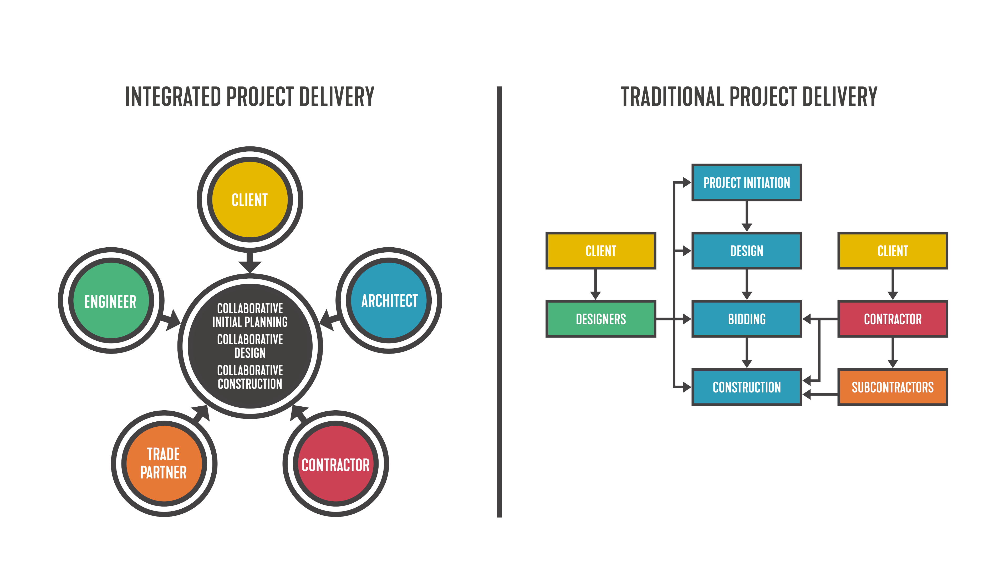
Integrated project delivery (IPD) is a lean construction method which aims to improve how different parties work together on a construction project. It focuses on better collaboration and communication among the owner, designer, builder and other trades and suppliers involved. This is different from the traditional project delivery method, where the owner has separate contracts with each party and acts as a middle person between the design and build teams.
This approach aims to get the most value for the owner, reduce unnecessary steps and make everything more efficient from the beginning of the design to the end of construction. By leveraging BIM in conjunction with IPD, the health-care design and construction industry can experience even more significant advancements, leading to more streamlined and successful projects. Figure 1 sheds light on the difference between integrated and traditional project delivery phases.

The BIM process for a traditional or non-IPD project might be described as follows: At project conception, the design team creates a model with three-dimensional content and pulls from that model to create its drawings. Contract documents are delivered with little-to-no trade partner input. The trade partner then takes the drawings and produces — oftentimes from scratch — a working model of its own. From that model, it creates shop drawings, which may be submitted back to the design team for review.
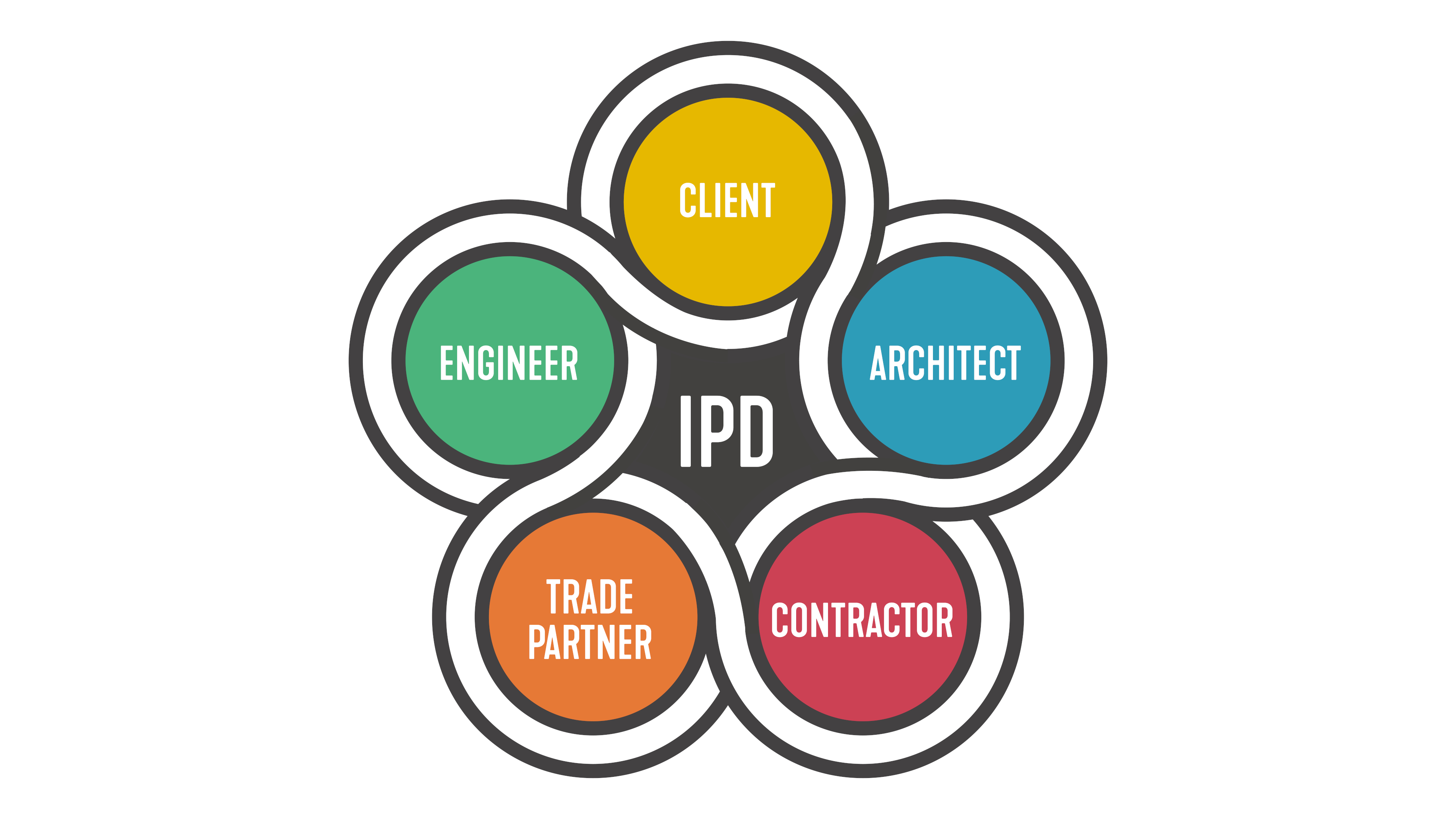
The BIM process for an IPD project might be described as follows (see Figure 2): At project conception, one party (generally the trade but sometimes the design team) creates one model for all parties to work and collaborate in. The design team then creates direction in the form of two-dimensional schematics, detail views, schedules and calculations.

The trade team populates the model with three-dimensional content, using direction from the design team’s content. Contract and permit documents remain separate from shop drawings, but they all pull from the same three-dimensional content.
Design teams comfortable with the non-IPD process may be hesitant to complicate things by agreeing to share a model with trade partners. In many ways, the non-IPD process is simpler, with clear and isolated responsibilities. Design and trade teams work in their silos, exchanging information only when necessary, if at all, and each work with their own tools.
Building information models can be finicky, and when it comes to model integrity, restricting access to limit file corruption, software malfunctions and simple unintended drawing changes is a reasonable strategy.
However, this simplicity can come at the cost of lost efficiency. This inefficiency can be seen in the form of duplicated work and personnel working outside of their core competencies, ultimately costing money, time or both.
Consider this: In the traditional process, two models are ultimately created. It is not efficient for the design team to build and maintain a model, only for the trade team to do the same thing after contract documents are received. If permit or contract drawings and shop drawings can both pull from the same model, why should two models be created and maintained?
Consider also the ability to better assign duties according to core competencies. Engineers tend to be good at things such as system calculations, code compliance and schematics. Generally, they are neither highly skilled nor efficient at drafting. They usually don’t have the “boots on the ground” experience that the trade team does, and so they’re not as well equipped to accurately convey details regarding pipe fittings, for example.
Regardless, in a traditional project, engineers are frequently forced to perform a task they’re not inherently skilled at in order to produce contract documents, only for their work to be redone in a separate model by someone more skilled and knowledgeable in areas such as drafting. In the IPD project BIM process, engineers can focus on engineering.
Less Conflict, Increased Accuracy and Innovation
Besides increased efficiency, other benefits can be found in the BIM process for an IPD project as previously outlined. If contract documents and shop drawings can both pull from the same model, fewer discrepancies will exist between them and less of an opportunity for conflict between the design and trade teams. There will be few, if any, surprises when the design team reviews the final shop drawings.
Additionally, there is an opportunity for increased detail and accuracy in the IPD project BIM process. For example, design teams frequently model piping systems in Revit native piping. It works nicely for plan views and to establish design intent, but it’s typically not very accurate for the purposes of clash detection because the pipe and fittings aren’t usually spatially accurate.
Because it benefits trade partners to be able to accurately model and price designs, they frequently maintain libraries of proprietary or at least spatially accurate pipe and fittings that they prefer to model with. When a project is modeled with the actual pipe and fittings that end up being installed, clashes are minimized, pricing is more accurate and as-built drawings better reflect reality.
Finally, the increased coordination between design and trade teams can open conversations leading to innovation. During a routine review of a recent health-care IPD project in process, the authors noticed that many water closets were connected to 3-inch waste piping. Although this was not against the applicable code, it was unusual. This sparked a conversation about why 3-inch water closet carriers were desired.
The design team was made aware that in certain circumstances, the difference in length between a 4-inch horizontal water closet carrier when connected to a 4-inch vertical sanitary tee and a 3-inch horizontal water closet carrier when connected to a 3-inch by 4-inch vertical sanitary tee was significant enough to require framing to need to be cut in the case of the 4-inch carrier and tee.
With this information, the design team chose to approve the use of the 3-inch carrier in certain circumstances where it would result in a cleaner design and where the distance to the 4-inch riser was limited. In the best-case scenario without the IPD project BIM process, this conversation would not have occurred this early in the design process.
Shared Model Concerns
The layering of design, layout and fabrication information and modeling provide higher accuracy and richer, more detailed three-dimensional components important for increased coordination, clash detection and other nontypical architectural and engineering purposes such as cost takeoffs and 4D scheduling. However, there is a cost and challenges to be borne by all parties involved.
A reasonable concern is that the extra data/model layer makes for a “heavier” model that may strain the computer resources of the BIM users. It becomes even more important to develop and enforce proper model management and BIM practices for all users working within a single model. These model management techniques can include low-hanging-fruit solutions like removing unused families, keeping view proliferation to a minimum, and performing other periodic model maintenance that will reduce model size and make teams more efficient.
However, other topics need to be addressed with a shared model. Two such topics are the number of users in a model can be a critical limiting factor for users, and ownership of elements in the model (who can change what and where). Understanding how the design team and the fabrication team work differently in Revit is key; just because all parties use the same software doesn’t mean we use it the same way.
It should be noted that model elements serve different purposes for different teams. Take, for example, a piece of plumbing or mechanical equipment. A design team might use a placeholder element lacking detailed geometric definition simply to claim space on the floor plan and to hold parameters that populate schedules for the basis-of-design equipment.
Later, as the design progresses, the trade partner might put in a more accurate model of the equipment it plans to submit. This creates a duplicate in the model, but they are vastly different elements serving different purposes. If one party was to delete the other’s, the results could be extremely detrimental to the design documents, coordination, or model takeoffs.
Ideally, the entire BIM team discussed these issues in advance and worked on a solution to allow placeholder equipment to evolve or be substituted smoothly to the trade teams’ equipment, keeping all the deliverables intact.
When design and trade teams maintained their own models, they were only modified by people within the respective teams. If something went wrong, there was no question as to what organization was at fault. With multiple legal entities working in a single model, opportunities to play the blame game when crashes occur abound.
Users should be well-trained in BIM software and understand how their actions affect other disciplines and users. This needs to be clearly spelled out in the BIM Execution Plan so the entire team knows which modeled content is theirs to modify and when.
The design team does share more control in the design process. In terms of plumbing, this tends to manifest itself in routing decisions. Ideally, design parameters should be given by the design team early in the project. This could be by way of early schematics to be eventually included in the contract documents. In any case, a feedback loop should exist as the design progresses for the design team to provide feedback to the trade team and vice versa.
While growing pains are to be expected, a more accurate model that serves as a single “source of truth” feeding both permit and shop drawings provides a better platform for coordination and, ultimately, a more polished finished product for the client.
Nathan Heitzinger, PE, CPD, is a plumbing engineer at SmithGroup’s Phoenix office. He is a member of ASPE and has more than seven years of experience in designing plumbing systems for various building types.
Arandeep Singh is a plumbing engineer at SmithGroup’s Dallas office. He is a member of ASPE and has more than one year of experience in designing plumbing systems for various building types.
Galen S. Hoeflinger is a technology strategist in SmithGroup’s Washington, D.C., office. He is a member of AIA’s Large Firm Roundtable and leads SmithGroup’s Technology in Practice - Delivery Solutions group. He has more than 24 years of experience in the architecture and engineering industry, filling various roles ranging from architect to BIM technologist.


