We have so many options to consider these days when designing or installing hydronic systems. The decisions our customers make can be daunting and are largely based on us, the contractor or the designer they’ve chosen.
Mod-con or conventional? HTP, Utica, Peerless, Burnham, Viessmann, Lochinvar, IBC, Weil-McLain, Slant/Fin, Navien, Triangle Tube or Bosch? Taco, Grundfos, Bell & Gossett, Wilo or Armstrong? Caleffi, tekmar, Belimo or Honeywell? Watts Radiant, Uponor, Viega or REHAU? Closely spaced tees, low-loss header, hydraulic separator, or keep piping it as you always have? Proper heat loss load calculation or some guy’s WAG?
There are plenty of choices for all of us and our often-stubborn opinions to go along with them. I have my favorites and you have yours. We each base those possibilities on our experiences, strengths, comfort level and business goals. And just because somebody’s course of action is different than yours doesn’t necessarily mean it’s bad. It’s just different.
That said, look at the options we can use to achieve a lower supply water temperature (SWT) for a zone or zones. In my experience, I’ve seen a bypass pipe used with a ball valve and a thermometer. Yes, I know; it’s not the greatest plan of attack ever devised. Then there are three-way thermostatic mixing valves, three-way motorized mixing valves, four-way motorized mixing valves, and a variety of injection mixing.
I’ve used most of these with varying degrees of accuracy and success. The reason I used the ball valve method when I first started is that it’s what an old-timer taught me. And I’m sure he used it because it’s what an even older old-timer taught him. That’s the way it sometimes goes until we learn a better way.
The last 15 years that I was in the field, I specified and installed mostly modulating-condensing boilers. If I had more than one design SWT, my choice of mixing was typically a three-way motorized mixing valve. For me, it was a reliable, accurate and fairly responsive method of going from a 140 degree SWT to a 90 degree SWT without sending my customer running for a Chapter 11 reorganization.
It’s funny how customers can be. One will tell you that expense is not a concern, and then they have an aneurism when you show them your proposal. Another will say they’re on a budget and then add on one thing after another until you’re doing a happy dance all the way to the bank. You never know.
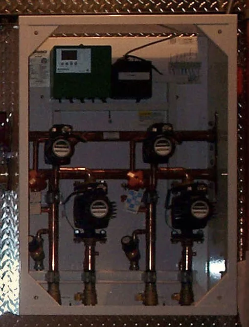
The tekmar three-way motorized valves or the Taco iSeries valves weren’t my only staples, though. I did my fair share of direct variable-speed injection (VSI) mixing. At first, I was using Wirsbo’s built-to-withstand-a-nuclear-bomb prefabbed panels, such as the Wirsbo 212, two-zone variable-speed injection panel (see Figure 1). I have some that are still going strong. I know this for a fact because I’m friends with a lot of former customers.
I’ve also gone the less-expensive method of building my own. I got away from VSI mixing and from what I’ve seen, many others have, too. It’s too bad because if you want to go from a reliable, accurate and fairly responsive method of mixing to a reliable, accurate and very responsive one, this would be a step in that direction.
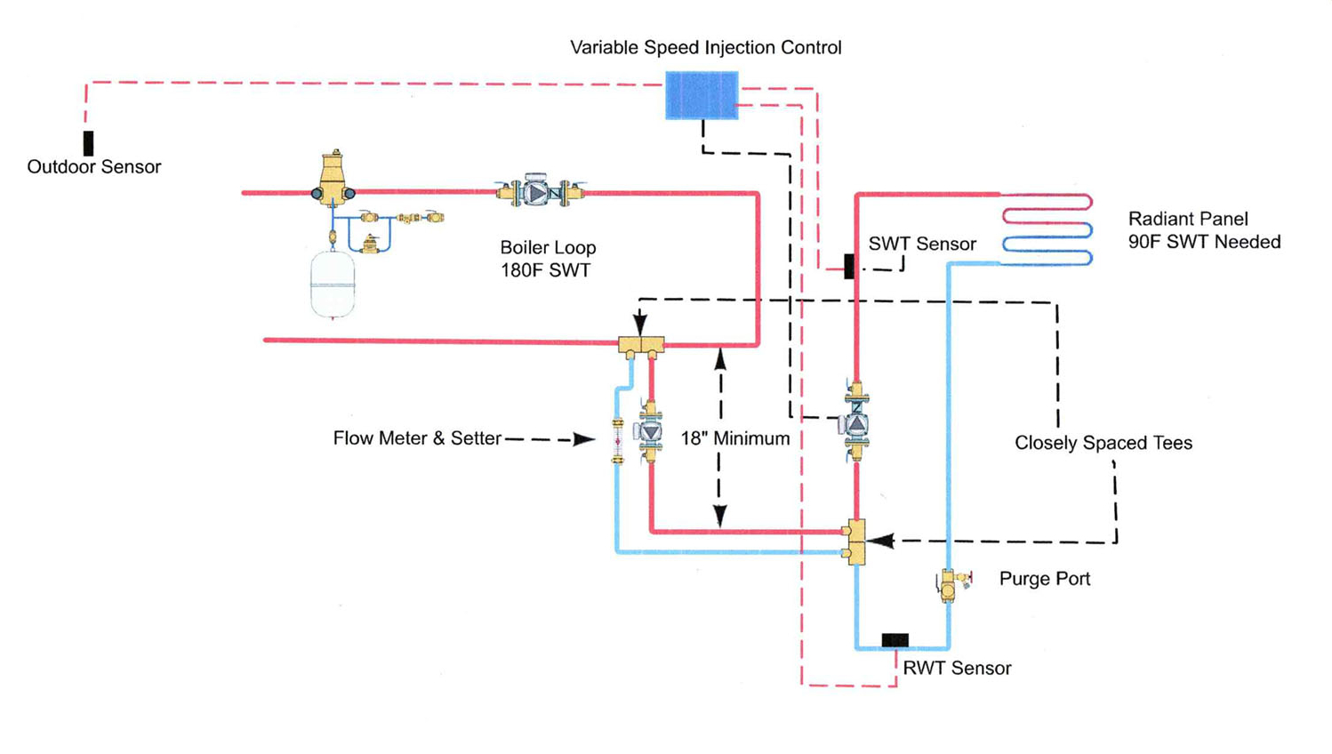
As with most things we do, the success lies in the details. You basically build an 18-inch bridge of 1/2-inch pipe from the higher-temperature boiler loop to the lower-temperature system loop, which, in this case, is a radiant floor panel. Check it out in Figure 2.
Let’s break it down into simple, easy-to-understand parts:
- First is the basic boiler loop, which includes an air separator, expansion tank, makeup water assembly and a circulator with integral flow check.
Nothing new here, but I’d add that I hope you’re using an air separator and pumping away from the point of no pressure change. Note that I didn’t choose the boiler because this could apply to almost any boiler that I can think of, and I didn’t add any system loops other than the one that we’re focusing on.
Feel free to use your hydronic imagination to trick this thing out any way you’d like.
- Second is another loop we see all the time: a low-temperature radiant panel complete with a circulator and purge port.
What connects those two loops is where we’re at today, so we’ll break it down even further with more detail. Every step is important. Details, details and more details. Trust me; if I can get it, you can get it.
Closely spaced tees
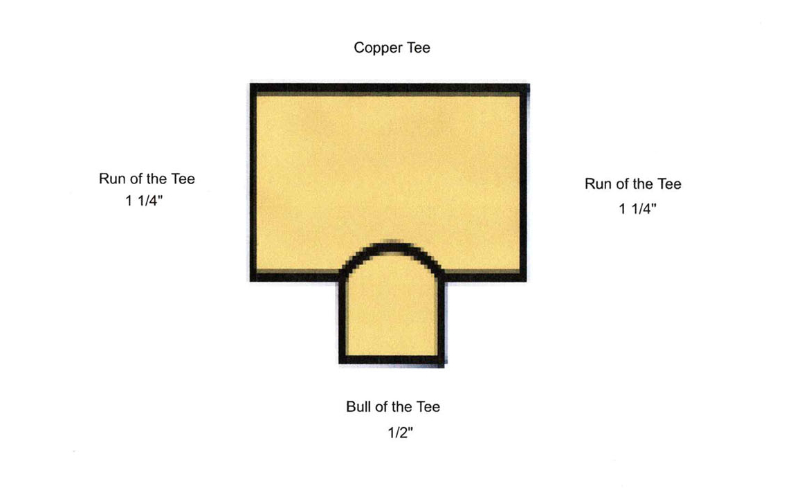
The different attempts at closely spaced tees I see on an almost daily basis continue to confound me, so I’m sharing this with you. On any tee fitting, you have the run of the tee and the bull (branch) of the tee, and they matter when it comes to hydraulic separation.
This would be called either a 1 1/4-inch x 1 1/4-inch x 1/2-inch copper tee or simply a 1 ¼-inch x ½-inch copper tee (Figure 3). It always reads run-run-bull. If the two runs are the same size, you don’t need the second description. When we talk about closely spaced tees, it means the runs of the tees are closely spaced, not the run on one tee to the bull of the other.
The other important part of closely spaced tees is that close means close, not just in the same area code. The closer the tees, the better. It means there’s less pressure drop between the tees, which provides better hydraulic separation — that’s the whole point. We don’t want pumps fighting each other. Here are the rules of spacing:
- Space between tees: Close as possible.
- Closely spaced tees after the circulator: Four times the pipe diameter (1-inch pipe = 4 inches).
- Closely spaced tees after 90-degree elbow: Six times the pipe diameter.
- Closely spaced tees before 90-degree elbow: Eight times the pipe diameter.
- Space between two sets of closely spaced tees: Eight times the pipe diameter.
On the diagram in Figure 2, between the sets of tees are the pipe risers; one is for the hotter water being injected into the radiant loop and the other is the cooler return water. We are moving small amounts of water, so the smaller wet rotor circulators using permanent split capacitors are what we’ll use, 1/25 horsepower or smaller. Even these are bigger than we need, so don’t think of going bigger.
Also, the circulator speed will be ramping up and down via the control, so don’t use a flow check on the injection pump. It’ll adversely affect the pump operation at lower speeds.
Note the 18-inch minimum drop on both risers. This is necessary to avoid downward thermal migration of the hot water when the pump is off.
As I mentioned previously, the flow through the injection risers is minimal, so 1/2-inch pipe works in many cases. To know for sure, you need to do math, which we’ll get to before you go for your next cup of coffee or bottle of beer.
Once we know the flow through the risers, we need to check it and set it. There are many options for this. The Caleffi Quick Setter is what I prefer, but the choice is all yours. This device also offers some head loss in a piping circuit that virtually wouldn’t have any without it.
Do the math
Closely spaced tees, 18-inch minimum risers, low gallons/minute (gpm), small pipe, little pumping power needed, and a way to set the flow — these are simple things we need to get right. Even if we screw up the math, it’s an easy fix if we get the basics right. Another way to look at it is in Figure 4.
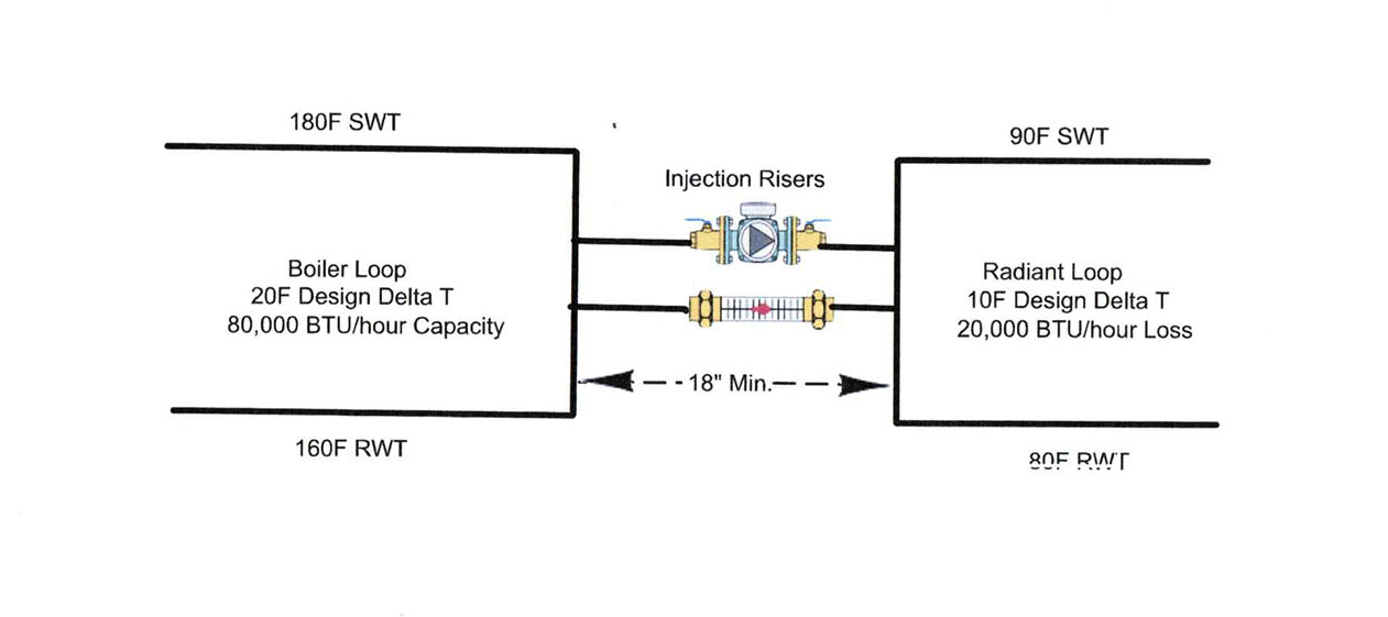
The VSI formula looks like this (there are variations of this formula, but they all arrive at the same value):
ƒ = (F1 x TD)
(T1 – TR)
ƒ = Injection flow required in gpm
F1 = Distribution flow rate 20,000 ![]() 5000 = 4 gpm
5000 = 4 gpm
TD = Distribution delta T = 10
T1 = Boiler supply water temperature injected into radiant panel = 180
TR = Return water temperature from radiant panel = 80
The gallons/minute is the value we need, and this is how we find it.
(4 x 10) 40
(180 – 80) = 100 = 0.4 gpm
That’s right — 0.4 gpm, less than a half-gallon of 180-degree water injected into our radiant panel loop to meet the heat loss. It’s easy to see why we need a specific control for this and a very small circulator, not to mention the need to check the flow and lock it in. A heat loss load calculation needs to be done before any of this because, without it, we wouldn’t know the target SWT for our radiant panel. If it were easy, anyone could do it.
The control will be getting feedback from the outdoor sensor for resetting the radiant panel SWT. The SWT sensor makes sure we’re getting the right mix of water to arrive at our 90 degree target temperature, and the boiler RWT sensor is a byproduct of our distribution loop design delta T.
If you don’t have the time to pipe your own injection assembly, manufacturers such as Taco, Viega, HPS and others offer them. The heating geek in me loves this method of mixing. Once you know your distribution system’s heat loss, design delta T and required supply water temperature, you’re ready to get piping — so grab your torch or press tool and have at it.