When it comes to radiant floor design, there’s a lot to know. There’s no way I can cover a complete radiant design in this column or this entire magazine for that matter. Most design manuals are in the 200-to-300-page range. But I’ll do my best to hit the highlights and the things to avoid at all costs.
I was part of a basement radiant installation as an apprentice in 1982. It was the first time I dipped my toes in a radiant floor experience. My job was simple. I had to tie strap the tubing as fast as humanly possible to the 6-inch by 6-inch wire mesh. I then realized my boss and his lead installer did everything as wrong as wrong can be.
How did I know this?
Because throughout the next two winters, I spent enough time at that house for it to qualify as my home address. The system never worked. Not at startup, not a week later, and certainly not a year and a half later when I moved on to a company opting for shorter loop lengths. It’s there I started digging into radiant heating books to educate myself on all things hydronic.
Here’s what I remember as the most significant mistakes on that first job:
1. Half-inch loops of tubing, 1,000 feet long.
2. Polybutylene tubing used without a heat exchanger or nonferrous pipe and components.
3. Couplings used randomly on kinked tubing that was to be embedded in 4 inches of concrete.
4. A cast-iron boiler was used without protection against low return water temperatures, such as a four-way mixing valve.
5. The tubing was never pressure-tested before the pour.
6. No insulation was used beneath the tubing and half the basement was of the walkout variety.
Those six things are more than enough to kill the radiant panel, the boiler and all the other components. I’m not sure how the ensuing lawsuit went, but South Barrington is at the top of high-society suburbs of Chicago, so I know the homeowners did not go gentle into that good night. I still remember the homeowner’s name, and I can’t remember what I had for dinner last night. That’s how epic this train wreck was.
My goal is to help you avoid these pitfalls and lead you in the direction of a successful radiant floor design and install every time.
Systematic design process
Like any successful hydronic design, there should be a step-by-step process to make sure you’ve covered everything you need to cover. It’s a lot easier to get it right the first time rather than having to correct it after the fact.
And with radiant floor heating, after the fact can be a nightmarish ordeal. Tubing is seldom easily accessible, so correcting loop lengths, kinks and leaks usually requires demolition of some sort. Nobody is going to be happy about that.
The other outcomes of poor design could include expensive stone or tile cracking, concrete cracking, hardwood floor failures, boiler short-cycling, boiler inefficiency due to high return water temperatures, early boiler failure, cold spots, lack of comfort one way or the other and the need for oversized pumps.
Below is the way I was taught to design radiant floor heating systems by some folks much smarter than I am. I’m going to pass along this information because it works, and we need our systems to work. This method is quick, accurate and shows you how to do it by hand.
Radiant design software is better because of how quickly you can manipulate the numbers and the fact that you can generate professional reports and material lists from them. But I think it’s worth knowing how the numbers work.
• Perform a room-by-room heat loss load calculation. Block loads usually don’t work very well with radiant floor design because it’s rare to have the same type of flooring throughout. You can have two identical rooms with identical heat losses, but they may require different supply water temperatures because of the finished floor. Heavy padding and thick carpeting are going to require higher water temperatures than one with tile or stone.
• Determine room thermostat setpoint temperature. This is usually 65-70 degrees for radiant floor systems, 65 degrees being the most common.
• Determine room square footage. Length multiplied by width equals the area.
• Determine the BTU/hour needed per square foot per room. Simply divide the room heat loss by the room square footage.
• Determine the floor surface temperature. Once you know the thermostat setpoint temperature and the BTU/hour/square foot, you can quickly determine the floor surface temperature by using this formula: (BTU/hr./sf ÷ 2) + setpoint temperature.
For example …
Setpoint = 65 degrees
Necessary BTU/hour/sf = 20
Constant for radiant floors = 2
65 + 20/2 = 65 F + 10 F = 75 degree floor surface temperature
• Choose an installation method. Extruded aluminum plates, staple-up or suspended tube (bad ideas), 4-inch concrete pour, 1 1/2-inch concrete overpour and knobbed mats are just a few examples.
• Choose tube type and size. As far as tube type is concerned, I prefer to stick with PEX-a because if you accidentally kink the tubing, it can be restored to its original shape by gently heating it. Heat guns are fine; torches are not. I’m also a big fan of PEX-Al-PEX. Once you form the bend, it stays bent without fear of it coming back and whacking you in the face. The installation method will determine the tubing size. Concrete applications typically use 1/2 inch and extruded plates can be 3/8 inch or 1/2 inch, depending on your preference. It’s much easier to work with 3/8-inch tubing, but the maximum loop lengths are shorter due to greater pressure loss.
• Determine floor covering R-value. Charts for these values are available at tubing manufacturers’ websites such as REHAU, Uponor or Mr. PEX.
• Determine design delta T. This is the target temperature difference between the supply water temperature and the return water temperature, typically 10 degrees in residential applications.
• Determine tube spacing. Most residential applications are going to be 6 inches, 8 inches, 9 inches or 12 inches, depending on the type of room, the room’s BTU/hr. needs and the installation method. Here’s how I usually attack this: For basements, it’s almost always 12 inches on center; extruded plates are invariably 8 inches. Concrete overpours vary between 6 inches, 9 inches and 12 inches, depending on the room heat loss and how low I want the supply water temperatures to be.
• Determine the supply water temperature. Four factors will provide us with this number: BTU/hour/sf; design delta T; installation method; and tube spacing. Tubing manufacturers provide charts.
• Determine active loop lengths and leader lengths. Loop lengths are calculated by using these multipliers:
1. 12 inches on center tubing x 1.0
2. 9 inches on center tubing x 1.33
3. 8 inches on center tubing x 1.5
4. 6 inches on center tubing x 2.0
Leader or tail lengths are the just distance between the room and the manifold times two. You’ll find some small differences in the recommended loop lengths, but you’ll be safe with these.
1. 3/8-inch tubing: 200 feet
2. 1/2-inch tubing: 300 feet
• Determine total gallons per minute. This one is easy, too. GPM = heat loss in BTU/(design delta T x 500). Example: 100,000/(10 x 500) = 100,000/5,000 = 20 GPM. 500 is a constant that comes from these values and equation:
1. There are 8.33 pounds in one gallon of water.
2. There are 60 minutes in an hour.
3. And 1 is the specific heat of water.
4. 8.33 x 60 x 1 = 499.8 (rounded up to 500)
• Determine GPM per loop. Total GPM/number of loops = GPM per loop
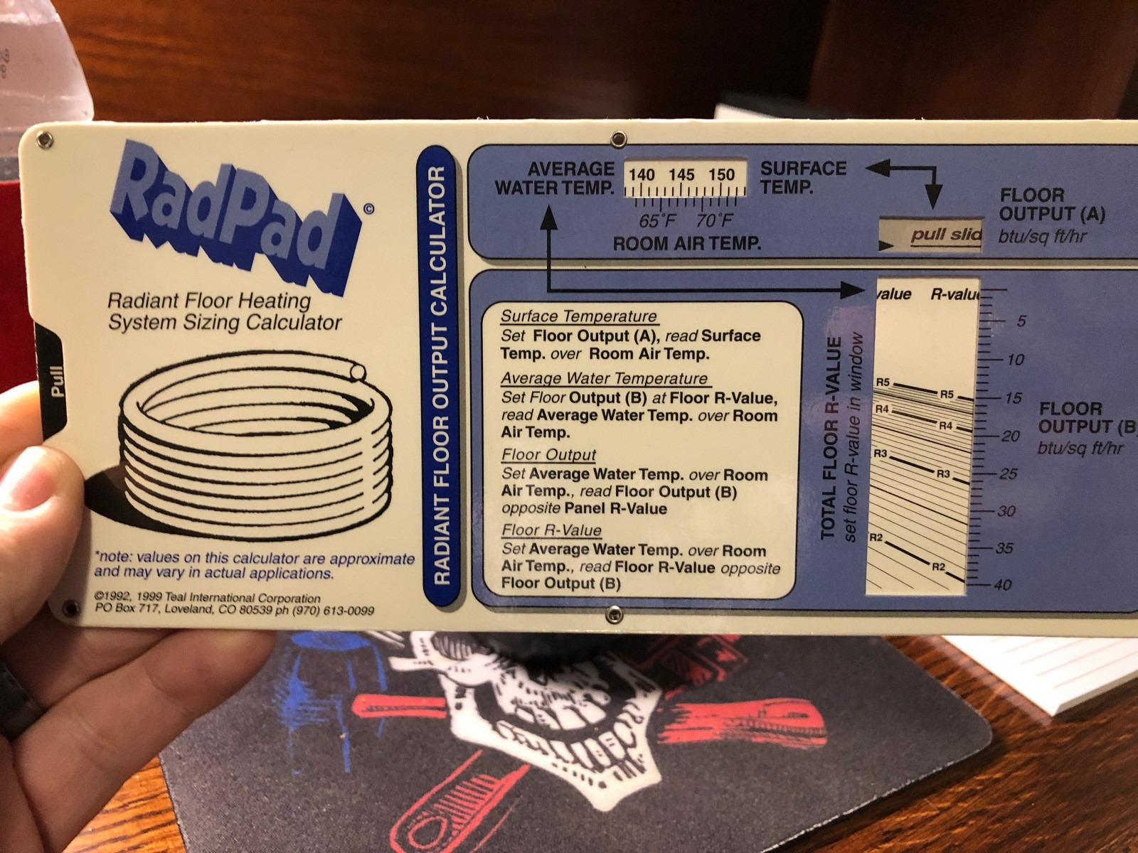
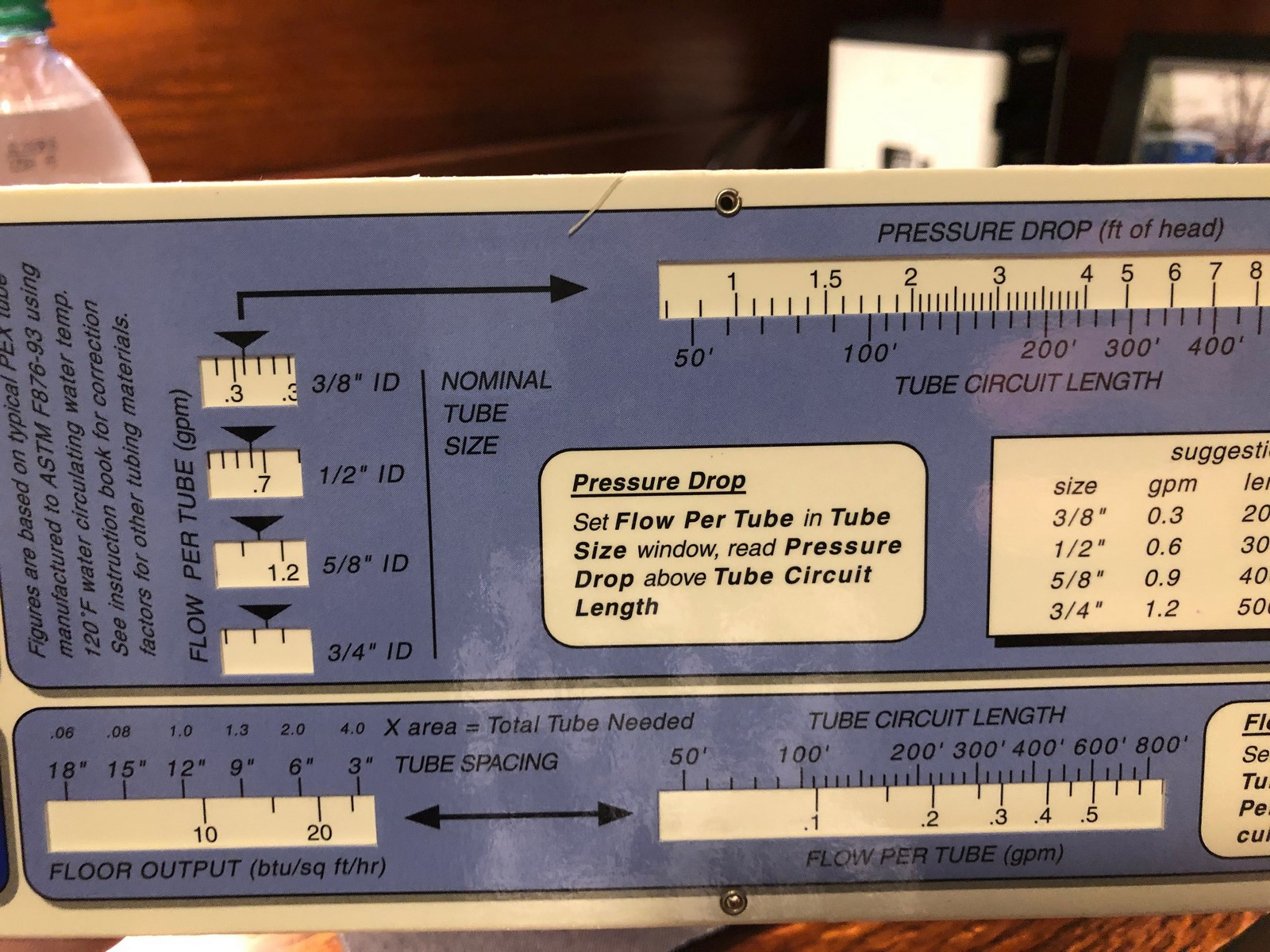
• Determine pressure loss or head loss. This is where most people might get overwhelmed a bit but don’t. It’s not necessary. There are so many calculators and tools to use that make it easy on you, but my favorite is the RadPad (see Figures 2 and 3).


The RadPad was originally made available by the RPA. This tool does it all and if I can figure it out, so can you. On the backside of this slide calculator, you just set the flow per tube in the nominal tube size window and then read the pressure loss above the tube circuit length.
A quick example and I mean quick, because it took me less than 10 seconds to get the answer: If my 1/2-inch tubing has a GPM of 0.6 and my tube circuit length is 265 feet, my pressure loss is roughly 4.3 feet. It’s that easy.
Get the app here: www.drakeip.com/RadPad/index.html
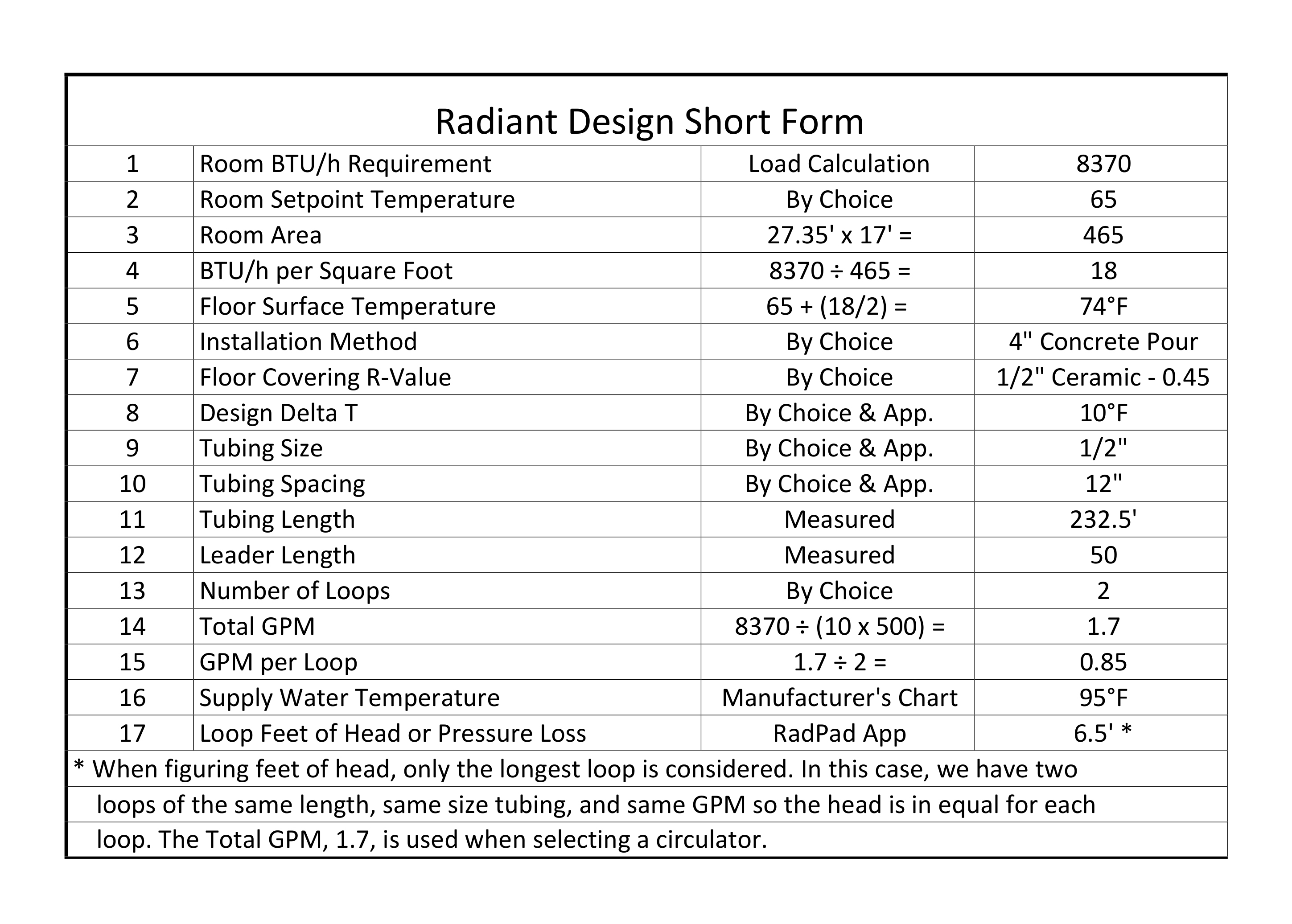
Let’s run through a complete design (see Figure 4).

This is exactly what I previously described, although shown in a single snapshot summary. It explains what you need, the way you arrive at that need and how you arrive at the result.
Something like this makes you dig in a little further than using software and helps you understand the process and math better. I know it did for me.
Things to know and avoid
• As I mentioned earlier, different floor coverings are often going to require different supply water temperatures. That said, do your best to limit the number of different water temperatures you’ll use in your design. Good mixing valves and circulators aren’t cheap. If I have design supply water temperatures with 10 to 15 degrees of one another, I’ll consider using a number in between if there are no foreseeable problems.
• Educate your customers and understand their expectations.
1. A well-designed system may not produce floors that will always warm their toes. Be sure they know that.
2. If they intend to put area rugs on the radiant heated floors, they need to know they’re blocking their only heat emitter. The bigger and thicker the rug, the worse it will be.
• Do your homework on hardwood floors. Check with the Radiant Professionals Alliance and the National Wood Flooring Association.
• If the floor covering is tile or stone, I’d recommend having the flooring contractor install an anti-crack membrane.
• Insulate below your radiant floor panel, no matter what type you choose. Buyer beware: Not all insulation performs as advertised. Follow generally accepted industry standards.
• If your loop lengths are not within 10 percent of each other, be sure to use manifolds that allow for balancing.
• Always pressurize your tubing and manifolds to 60 psi as soon as they’re installed.
• Keep in mind that if you use a glycol/water mixture, you’ll need more pump. The specific heat of water is 1.0. The water/glycol mixture is at least 10 percent higher.
• When installing tubing on top of the subfloor for a 1 1/2-inch overpour, be careful to not place all your homeruns in the common hallway. If you do so, the hall will overheat; it’s probably where your thermostat is located. I prefer to drill and place them under the floor. If that’s not possible, insulate the majority, if not all, the tubing. Your room-by-room load calculation will dictate how much to insulate.
• The closer you keep your on-center tube spacing, the lower supply water temperatures you’ll need.
• Maximize your modulating condensing boiler efficiency by getting your return water temperatures (RWT) as low as possible. The lower the RWT, the more the boiler will be in condensing mode. The longer the boiler is in condensing mode, the more efficient it will be.
• There’s no need to install tubing beneath kitchen cabinets or appliances, but keep your eyes peeled for the last-minute desk niche added to the cabinetry. You’ll want tubing there. Ask me how I know that. It was an oversight of mine in 1995, and I was constantly reminded of my 2-foot by 2-foot mistake.
You don’t want to be on the wrong end of litigation, so if you choose to become a radiant contractor, go all in. Read, go to seminars, ask questions, listen and learn, and you’ll never need to worry about it.


